Introduction: The Joining Challenge Driving FDS Adoption
Flow drill screwing in automotive manufacturing has emerged as a pivotal joining solution for one fundamental reason: modern vehicle architectures increasingly combine aluminum extrusions, high-strength steel stampings, and cast magnesium in a single body-in-white structure — and no conventional fastening method can connect these dissimilar materials from one side, without pre-drilled holes, in under two seconds.
Traditional resistance spot welding demands two-sided electrode access and cannot bridge aluminum-to-steel interfaces. Self-piercing riveting requires matched die sets beneath the joint and adds permanent weight. Adhesive bonding introduces cure-time bottlenecks incompatible with 60-second takt times. Flow drill screwing in automotive body construction eliminates each of these constraints through a thermo-mechanical process that generates its own mounting hole, forms mating threads in the displaced material, and delivers a torque-controlled clamped joint — all within a single automated cycle.
This article examines the engineering parameters that govern FDS screw design, joint performance, and process control, with particular emphasis on how precision fastener manufacturers contribute to the expanding deployment of flow drill screwing in automotive programs worldwide.
How the Flow Drill Screwing Process Works
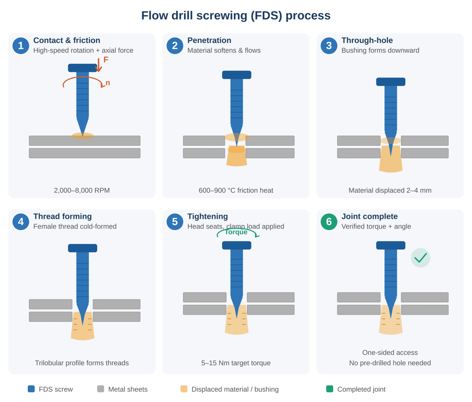
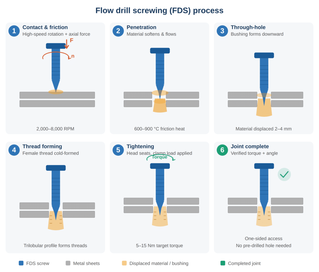
The FDS cycle progresses through six distinct mechanical phases. Understanding each phase is essential for specifying the correct screw geometry, base-material combination, and driving-system parameters.
| Phase | Screw Action | Material Response | Duration (Typical) |
|---|---|---|---|
| 1 — Contact & Friction Heating | Screw tip rotates at 2,000–8,000 RPM under 1.0–3.5 kN axial load | Sheet surface heats to 600–900 °C via frictional energy input | 0.3–0.8 s |
| 2 — Penetration | Tapered tip displaces softened material radially and axially | Top sheet deforms plastically; material begins flowing downward | 0.3–0.6 s |
| 3 — Through-Hole Formation | Screw nose fully penetrates bottom sheet | Displaced metal forms a downward-protruding bushing (2–4 mm) | 0.2–0.4 s |
| 4 — Thread Forming | Thread-forming zone engages bushing wall | Internal female threads are cold-formed into the bushing bore | 0.2–0.4 s |
| 5 — Tightening | Speed reduces; torque ramps to target value | Screw head seats against top-sheet surface, establishing clamp load | 0.2–0.3 s |
| 6 — Final Torque & Angle Check | Controller verifies torque and rotation angle within acceptance window | Joint reaches target preload; process signature logged | 0.1–0.2 s |
Total cycle time for a standard aluminum-to-aluminum FDS joint typically falls between 1.5 and 2.5 seconds — comparable to resistance spot welding and significantly faster than adhesive-bonded or rivet-bonded alternatives.
Screw Geometry: The Five Critical Zones
An FDS fastener is not a commodity tapping screw with a pointed tip. Each region of the screw body performs a specific thermo-mechanical function. Dimensional inaccuracy in any zone degrades joint strength, increases driving torque beyond equipment limits, or causes premature tip fracture.
| Screw Zone | Geometric Feature | Functional Role | Key Dimensional Parameters |
|---|---|---|---|
| Friction Tip | Conical nose (60°–90° included angle) | Generates frictional heat to soften sheet material | Tip diameter: 2.0–3.5 mm; cone angle tolerance: ±1° |
| Pilot Section | Smooth cylindrical shank below cone | Guides penetration path; stabilizes lateral wander | Diameter: 0.90–0.95 × nominal; length: 3–6 mm |
| Thread-Forming Zone | Trilobular or multi-lobe cross-section | Displaces material to create female thread without cutting | Lobe height: 0.05–0.12 mm above pitch diameter |
| Clamping Shank | Cylindrical body between thread and head | Provides elastic stretch zone for clamp-load retention | Shank length calibrated to total stack thickness ±0.3 mm |
| Head & Bearing Surface | Flat or flanged head with drive recess | Distributes clamp force; interfaces with driving tool | Head OD: 10–16 mm; bearing flatness ≤ 0.05 mm TIR |
The trilobular thread-forming profile deserves particular attention. Unlike cut-thread tapping screws that remove material as chips, the trilobular geometry displaces parent metal radially — cold-forming the female thread with continuous grain flow. This displacement mechanism produces threads with 30–40 % higher strip-out resistance compared to cut threads of identical nominal diameter, a performance margin that directly enhances the pull-out strength of flow drill screwing in automotive structural joints.
Material Combinations and Joint Stack-Ups
Flow drill screwing in automotive body assembly must accommodate a diverse matrix of material pairings. Joint performance varies dramatically depending on which material occupies the top (entry) sheet versus the bottom (bushing-forming) sheet.
| Stack-Up Configuration | Top Sheet | Bottom Sheet | Typical Bushing Length | Pull-Out Force (Typical) | Key Application |
|---|---|---|---|---|---|
| Al–Al | 6016-T4 (1.0–2.0 mm) | 6016-T4 (1.5–3.0 mm) | 3.5–5.0 mm | 3.5–5.5 kN | Door inner to reinforcement |
| Al–Steel | 6016-T4 (1.0–1.5 mm) | DP590/DP780 (1.0–2.0 mm) | 2.5–4.0 mm | 5.0–8.0 kN | Roof rail to side panel |
| Al–Al–Al (3-layer) | 5182-O (1.0 mm) + 6016-T4 (1.5 mm) | 6016-T4 (2.0 mm) | 4.0–6.0 mm | 4.0–6.5 kN | Multi-piece closure assembly |
| Steel–Steel (thin gauge) | CR340 (0.8–1.2 mm) | DP590 (1.0–1.5 mm) | 2.0–3.5 mm | 6.0–9.0 kN | Instrument panel cross-car beam |
| Al–Cast Mg | 6016-T4 (1.2 mm) | AM60B die-cast (3.0 mm) | 3.0–4.5 mm | 2.5–4.0 kN | Liftgate inner to cast frame |
| CFRP–Al (with pilot hole) | CFRP composite (1.5–2.5 mm) | 6016-T4 (2.0 mm) | 3.5–5.0 mm | 3.0–5.0 kN | Composite panel to aluminum sub-frame |
Two rules emerge from production experience. First, the softer or thinner material should occupy the top-sheet position whenever possible, because the friction tip penetrates it more readily and with lower axial thrust — reducing the risk of sheet deformation beyond the immediate joint zone. Second, composite (CFRP) top sheets require pre-drilled pilot holes to avoid delamination; flow drill screwing in automotive CFRP applications is therefore a hybrid process rather than a fully pilot-hole-free technique.
Screw Material and Hardness Specifications
The FDS screw itself endures extreme conditions: tip temperatures approaching the solidus of aluminum (≈ 580 °C), torsional loading during thread forming, and sustained clamping stress thereafter. Screw metallurgy must satisfy each phase simultaneously.
| Screw Property | Specification Requirement | Functional Justification |
|---|---|---|
| Base Material | Case-hardening steel (e.g., 20MnB4, 22MnB5) | Boron-steel grades provide through-hardenability for small cross-sections |
| Surface Hardness (Tip & Thread) | 450–580 HV (≈ 45–55 HRC) | Resists abrasive wear during friction drilling and thread forming |
| Core Hardness (Shank) | 300–400 HV (≈ 30–40 HRC) | Retains toughness to absorb dynamic loads without brittle fracture |
| Carburized Case Depth | 0.15–0.40 mm | Sufficient wear layer without embrittling the load-bearing core |
| Hydrogen Content (Post-Plating) | ≤ 2.0 ppm (baked within 4 hours) | Prevents hydrogen-induced delayed fracture in service |
| Torsional Strength (Minimum) | ≥ 8.5 Nm (M5); ≥ 16 Nm (M6) | Must exceed maximum thread-forming torque by safety margin |
| Fatigue Endurance Limit | ≥ 10⁷ cycles at 50 % of proof load | Withstands body-structure vibration over vehicle lifetime |
The differential hardness profile — hard case over tough core — is non-negotiable for FDS performance. A screw that is uniformly hard will fracture during torsional thread-forming. A screw that is uniformly soft will wear its tip geometry within the first penetration phase, producing oversized holes with insufficient thread engagement.
KeyFixPro engineers this dual-hardness architecture through precisely controlled carburizing cycles followed by oil quench and low-temperature temper, with case depth verified by Vickers micro-hardness traverses at 0.05 mm intervals on metallographic cross-sections from every production lot.
Process Parameters and Quality Control Windows
Automated FDS driving systems monitor multiple parameters in real time. Joint quality depends on maintaining each variable within defined acceptance corridors.
| Process Parameter | Typical Operating Range | Effect of Below-Range Value | Effect of Above-Range Value |
|---|---|---|---|
| Spindle Speed (Drilling Phase) | 2,000–8,000 RPM | Insufficient heat generation; incomplete penetration | Excessive heat; material melting; oversized bushing bore |
| Axial Force (Drilling Phase) | 1.0–3.5 kN | Slow penetration; extended cycle time | Sheet buckling; material extrusion beyond joint zone |
| Thread-Forming Speed | 500–2,000 RPM | Poor thread definition; low strip-out strength | Thread over-forming; risk of screw torsional failure |
| Final Torque | 5–15 Nm (application-dependent) | Under-clamped joint; vibration loosening risk | Head embedment; top-sheet cracking around head bearing |
| Seating Angle | 30°–720° (application-dependent) | Insufficient preload | Stripped threads; loss of clamp integrity |
| Cycle Time (Total) | 1.5–2.5 seconds | N/A (faster is acceptable if quality windows met) | Process instability; indicates abnormal resistance |
Every FDS installation generates a characteristic torque-angle-time process curve. Statistical process control systems compare each curve against a master signature, flagging outliers for immediate investigation. This real-time monitoring capability makes flow drill screwing in automotive production one of the most traceable joining methods available — each joint is individually verified, unlike sampling-based inspection regimes typical of riveted or welded structures.
Comparative Advantages Against Alternative Joining Methods
| Performance Criterion | Flow Drill Screwing | Self-Piercing Riveting (SPR) | Resistance Spot Welding (RSW) | Adhesive Bonding |
|---|---|---|---|---|
| One-Sided Access | Yes | Yes (but requires die beneath) | No (requires dual electrodes) | Yes |
| Pre-Hole Required | No (standard Al/Steel) | No | No | N/A |
| Dissimilar Metal Capability | Excellent (Al–Steel, Al–Mg) | Good (limited by die selection) | Poor (similar metals only) | Excellent |
| Removability / Serviceability | Yes (standard screw removal) | No (permanent deformation) | No (destructive separation) | Difficult (adhesive removal) |
| Cycle Time | 1.5–2.5 s | 1.5–3.0 s | 0.3–1.0 s | Minutes to hours (cure) |
| Joint Traceability | Individual (torque-angle curve per joint) | Batch-level | Batch-level (weld current log) | Batch-level |
| Weight Added per Joint | 3–6 g (screw only) | 3–5 g (rivet only) | 0 g (fused material) | 1–3 g (adhesive film) |
| Waterproof Seal Capability | Optional (with sealing washer) | Limited | Inherent (fused) | Excellent |
The removability advantage is increasingly significant as automotive OEMs design for recyclability under EU End-of-Life Vehicle directives. Flow drill screwing in automotive body structures allows damaged panels to be unbolted and replaced without destroying the surrounding structure — a repair paradigm impossible with riveted or welded joints.
KeyFixPro’s Role in the FDS Supply Chain
While the driving equipment and process programming reside with system integrators (DEPRAG, Weber, Atlas Copco), the FDS screw itself must be manufactured to exacting metallurgical and dimensional standards by a precision fastener specialist. This is where KeyFixPro contributes.
Cold Forging Expertise — KeyFixPro’s multi-station progressive cold headers form the complex FDS screw geometry — friction tip, trilobular thread-forming zone, clamping shank, and flanged head — from boron-steel wire in a single continuous forming sequence. Ambient-temperature forging preserves uninterrupted grain flow through the critical tip-to-shank transition, delivering torsional strength 40–60 % above machined equivalents. Material utilization reaches 98 %.
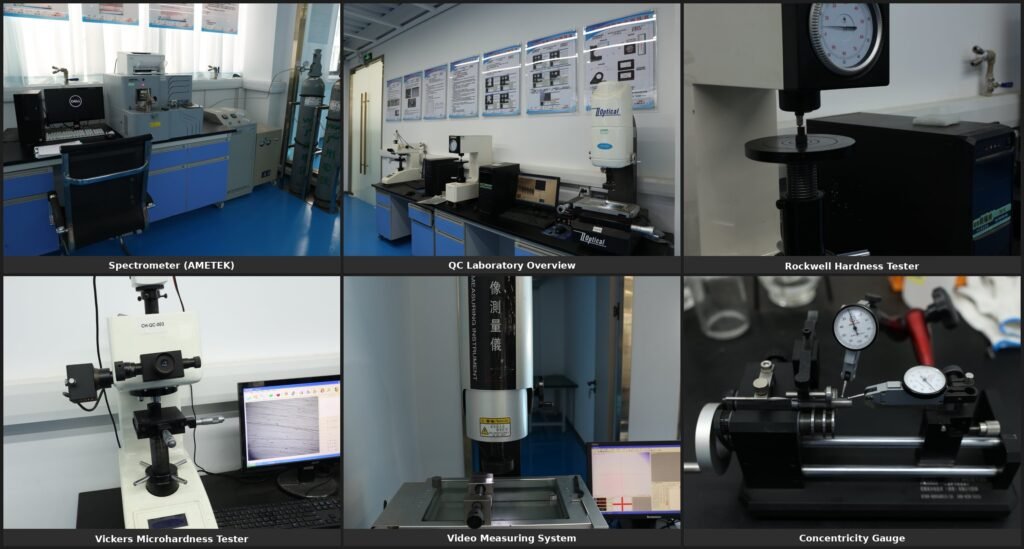
Heat Treatment Control — In-house carburizing furnaces with atmosphere-controlled endothermic gas produce the precise case-depth profiles (0.15–0.40 mm) that FDS screws demand. Every lot undergoes Vickers micro-hardness traverse verification and metallographic examination.
Dimensional Assurance — CNC secondary operations on STS C-series 5-axis centers hold ±0.005 mm positional accuracy on drive recesses and head-bearing surfaces. CMM inspection at ±0.001 mm resolution plus 100 % optical sorting ensures that every shipped screw conforms to the geometry specifications that FDS driving systems depend on.
Surface Treatment — Zinc-nickel alloy plating validated to 1,000+ hours neutral salt spray (ASTM B117) protects FDS screws against under-body and engine-bay corrosion. Post-plating hydrogen-relief baking within 4 hours of coating eliminates delayed-fracture risk.
Quality System — IATF 16949, ISO 9001, and ISO 14001 certifications underpin full PPAP-level documentation, digital per-lot traceability, and a sustained 0 PPM field-defect record across 100+ completed automotive programs.
Frequently Asked Questions
What makes flow drill screwing in automotive different from ordinary self-tapping screw assembly?
FDS combines friction drilling and thread forming in one operation. The screw’s rotating tip generates 600–900 °C frictional heat to soften and displace sheet metal, creating both the mounting hole and a threaded bushing simultaneously — no pre-drilled hole or back-side nut is needed. Conventional self-tapping screws require an existing hole and do not form a bushing.
Which vehicle programs currently use flow drill screwing?
FDS is deployed across multiple global OEM platforms for body-in-white, closure, and EV battery-tray assembly. Notable adopters include German premium manufacturers for aluminum-intensive body structures and North American EV programs for mixed aluminum-steel battery enclosure joints.
Can flow drill screws be removed and reinstalled?
Yes. Because the bushing retains its formed female thread, a standard metric screw of equivalent diameter and pitch can be threaded into the same hole during service or repair — a key advantage over permanent joining methods like riveting or spot welding.
What screw sizes are most common for automotive FDS applications?
M4, M5, and M6 diameters account for the vast majority of automotive FDS installations, with lengths ranging from 16 mm to 35 mm depending on total stack thickness. KeyFixPro maintains cold-heading tooling across this full size range.
KeyFixPro — established in 2000, IATF 16949 / ISO 9001 / ISO 14001 certified — delivers precision cold-forged and CNC-finished fasteners for flow drill screwing in automotive body structures and beyond. With 25+ years of manufacturing heritage, 50+ patents, 20+ senior engineers, and ±0.001 mm inspection capability, KeyFixPro supports OEM and Tier 1 programs across 20+ countries. Visit www.keyfixpro.com or contact sales@keyfixpro.com.