
Thread forming screws for die cast aluminum let engineers skip tapping and still get a strong, chip-free thread in an ECU housing, inverter case or motor cover. The screw rolls its own thread into a cored hole, so there is no tapping step, no chip cleaning and no loose aluminum near the electronics. The joint only works when the hole, the screw and the torque window are designed together. This guide covers all three.
Key Takeaways
- A thread forming screw displaces material to make its internal thread instead of cutting it. In aluminum die castings, that means no chips and a work-hardened thread flank.
- Published die-cast tables for trilobular screws put the cored hole at roughly 0.93 × d at the top and about 0.89–0.90 × d at the bottom, with at least 2 × d of engagement.
- Keep cored holes rather than drilling them. The dense cast skin around a core pin forms better threads than the porous core of a thick section.
- Set tightening torque between the highest drive torque and the lowest strip torque measured in real castings. A strip-to-drive ratio of 3:1 or more is a common design target.
- Zinc-flake coatings to ISO 10683:2018 add no hydrogen to case-hardened screws and help control galvanic corrosion against aluminum.
Contents
- What are thread forming screws?
- Why use thread forming screws for die cast aluminum?
- How should the cored hole be designed?
- How do you set the torque window?
- Which coating and material should you specify?
- Why do these joints fail?
- How are thread forming screws manufactured?
- What should the drawing or RFQ specify?
- Frequently Asked Questions
What are thread forming screws?
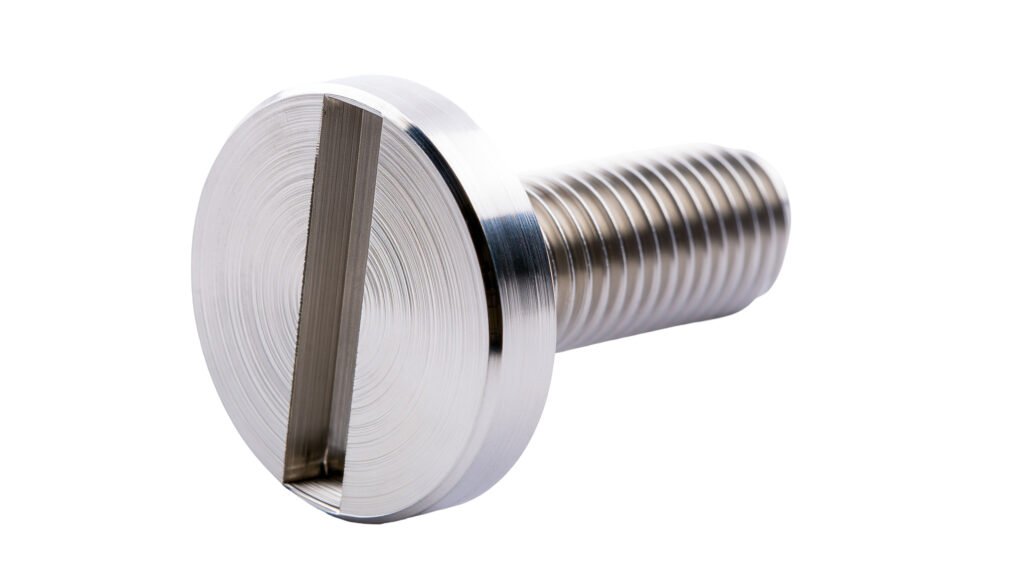
A thread forming screw is a hardened screw that creates its mating internal thread by cold-flowing the hole wall, without removing material. Most designs for metal use a trilobular (three-lobed) cross section. The lobes form the thread one point at a time, so drive torque stays low and the relaxed material grips the flats afterwards. That grip adds resistance to vibration loosening.
They are also called thread rolling screws. For ISO metric threads they are specified in DIN 7500-1:2021; proprietary trilobular forms follow the same principle with their own lobe geometry.
| Fastening method | Hole preparation | Chips | Typical use in die castings |
|---|---|---|---|
| Thread forming screw | Cored or drilled hole, no tapping | None | High-volume housings, covers, electronics |
| Thread cutting screw | Cored or drilled hole | Yes, from the cutting flutes | Brittle materials where forming would crack |
| Tapped hole plus machine screw | Drill and tap | Yes, from tapping | Joints serviced many times |
| Threaded insert plus machine screw | Hole for insert | Depends on insert type | Frequent service, high clamp load |
Why use thread forming screws for die cast aluminum?
Thread forming screws for die cast aluminum remove the tapping operation and its chips. In an electronics housing, a stray aluminum chip can bridge conductors on a board. A formed thread also has a work-hardened flank, which typically gives higher strip resistance than a cut thread in the same hole.
The trade-off is that die-cast alloys such as EN AC-46000 (AlSi9Cu3(Fe)), A380 and ADC12 have low elongation, typically only a few percent. They form threads well, but a boss with too little wall cracks before it yields. The hole and boss design therefore matter more than in wrought aluminum. For housing design and casting process notes, see our guide to custom die cast parts.
How should the cored hole be designed?
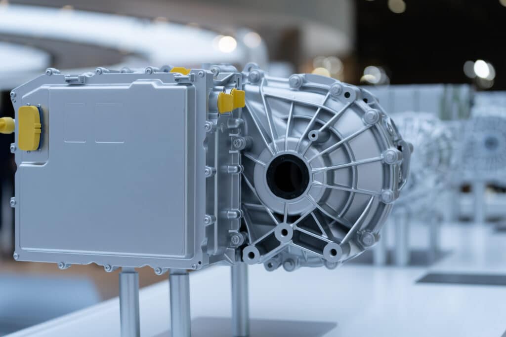
Design the hole for thread forming screws for die cast aluminum as a cored, tapered hole sized for 65–75 % thread engagement, with a relief at the entry and engagement of at least twice the screw diameter. The core pin needs draft to eject, so the hole is slightly larger at the top than at the bottom. Screw makers publish hole tables for this taper.
Published TAPTITE II die-cast tables, which cover inch sizes, work out to a top diameter of about 0.93 × d and a bottom diameter of about 0.89–0.90 × d. Applied to metric sizes, the same ratios give the starting points below. Confirm the final values against your screw supplier’s table and trials in production castings.
| Screw size (d) | Cored hole top, approx. | Cored hole bottom, approx. | Minimum engagement (2 × d) |
|---|---|---|---|
| M3 | 2.79 mm | 2.68 mm | 6 mm |
| M4 | 3.72 mm | 3.58 mm | 8 mm |
| M5 | 4.65 mm | 4.47 mm | 10 mm |
| M6 | 5.58 mm | 5.37 mm | 12 mm |
| M8 | 7.44 mm | 7.15 mm | 16 mm |
Four more rules apply to the boss around the hole:
- Boss outer diameter: about 2–2.5 × d is a common starting point. Thinner walls crack under the hoop stress of forming.
- Entry relief: a short counterbore slightly larger than d stops displaced material from lifting under the screw head and protects the edge from chipping.
- Hole depth: allow extra depth beyond the engagement length so the screw point and any debris do not bottom out.
- Cored, not drilled: drilling removes the dense skin that forms against the core pin and can open subsurface porosity in thick sections.
Engineer’s Note: Measure the cored hole in castings from every cavity of the die, not just the first-off part. Core pins wear, and a hole that drifts 0.05 mm oversize can drop strip torque noticeably.
How do you set the torque window?
Set the tightening torque between the highest drive torque and the lowest strip torque measured in real castings. Drive torque is what the screw needs to form the thread. Strip torque is where the formed thread fails. The wider the gap between them, the more tolerant the assembly is of hole, coating and casting variation.
| Torque term | Meaning | How to get it |
|---|---|---|
| Drive torque (Td) | Peak torque while forming, before the head seats | Torque-angle trace on sample castings |
| Strip torque (Ts) | Torque at which the formed thread fails | Tighten to failure in sample castings |
| Tightening torque (Tt) | Production setting on the driver | Above max Td with margin, well below min Ts |
| Strip-to-drive ratio | Ts ÷ Td | 3:1 or more is a common design target |
Re-use needs the same discipline. Strip torque usually falls each time a screw is re-driven into its formed thread, so test it after the number of re-installations the service manual allows and put that limit on the drawing.
Common Pitfall: Changing the coating or topcoat after validation changes the friction, and with it both drive torque and clamp load. Treat any coating change as a new validation.
Which coating and material should you specify?
For thread forming screws for die cast aluminum, specify case-hardened carbon steel with a zinc-flake coating to ISO 10683:2018 for most aluminum housings. The steel must be much harder than the casting to form a thread, and zinc flake applies without electroplating, so it adds no hydrogen. It also gives a barrier between steel and aluminum.
| Coating | Hydrogen risk on hardened screws | Galvanic behavior on aluminum | Notes |
|---|---|---|---|
| Zinc flake (ISO 10683:2018) | None from the process | Good; zinc is close to aluminum in potential | Topcoat sets friction; salt spray 1,000 h+ depending on system |
| Zinc-nickel electroplate | Needs baking after plating | Good | Common in automotive under-hood parts |
| Black oxide | Low | Poor | Indoor, dry equipment only |
Stainless steel screws resist corrosion but cannot be case hardened, so most thread forming designs for aluminum stay in carbon steel. For one-sided joining of sheet rather than castings, compare flow drill screws for aluminum.
Why do these joints fail?
Most failures of thread forming screws for die cast aluminum trace back to the hole, not the screw.
| Failure | Root cause | Prevention |
|---|---|---|
| Boss cracks during driving | Wall too thin or hole undersize | Boss OD about 2–2.5 × d; check hole at the bottom of its tolerance |
| Thread strips at tightening | Hole oversize, worn core pin or porosity | Measure holes per cavity; keep holes cored; widen the torque window |
| Screw breaks while driving | Drive torque too high from a small hole or long engagement | Verify hole size and engagement length; check hardness and case depth |
| Joint loosens in vibration | Low clamp load or relaxation of the casting | Validate clamp load; consider a flange head to spread load |
| Corrosion at the joint | Steel in direct contact with aluminum in a wet environment | Zinc-flake coating; seal the head area |
How are thread forming screws manufactured?
Thread forming screws are cold headed, rolled to the trilobular form, then case hardened and coated. The hard case over a tougher core lets the screw form threads without snapping.

KEYFIX produces thread forming screws for die cast aluminum on 25 cold heading machines and 22 thread rolling machines that roll threads from M1.2. Heat treatment covers case hardening and carbonitriding within a hardness range of HRC 28–62, and coatings include zinc flake and zinc-nickel to specification. Threads are checked with go/no-go gauges, Torx recesses with T10–T45 gauges, and outgoing inspection runs at AQL 0.4 against a target below 25 PPM, under IATF 16949 (audited by NQA). Drive-torque and strip-torque tests in your castings are arranged through third-party testing laboratories. See our cold forged parts and inspection standards pages, and lightweight fasteners for EV programs.
What should the drawing or RFQ specify?
A complete RFQ for thread forming screws for die cast aluminum includes:
- Thread size, length and thread form (trilobular or a named proprietary form).
- Head style, drive (for example Torx T25) and any captive washer.
- Material, case depth and surface and core hardness.
- Coating system, topcoat and friction requirement.
- Casting alloy and the cored hole drawing, top and bottom diameters included.
- Required drive torque, strip torque and tightening torque, or the test method to establish them.
- Number of re-installations to validate.
- Annual volume per size.
Frequently Asked Questions
Can thread forming screws be used in die cast aluminum?
Yes. Die-cast aluminum alloys such as A380, ADC12 and EN AC-46000 form threads well when the cored hole is sized for 65–75 % thread engagement and the boss wall is thick enough. The screw must be case hardened so it is much harder than the casting.
What hole size do thread forming screws need in die cast aluminum?
Published die-cast tables for trilobular screws put the cored hole at roughly 0.93 × d at the top and about 0.89–0.90 × d at the bottom. For an M5 screw that is about 4.65 mm and 4.47 mm. Confirm the final values with the screw supplier’s table and trials in production castings.
What is the difference between thread forming and thread cutting screws?
A thread forming screw displaces material to create the thread and produces no chips. A thread cutting screw has flutes that cut the thread and produce chips. Thread forming suits ductile metals such as die-cast aluminum, while thread cutting suits brittle materials that would crack.
Can a thread forming screw be removed and reinstalled?
Yes. Re-driven into its own formed thread, the screw follows the existing thread, but strip torque usually falls with each cycle. Validate the number of re-installations the service manual requires and test strip torque after the last one.
Should cored holes be drilled out before assembly?
No, in most cases. The cast skin around a core pin is denser than the interior of a thick section, and drilling removes it and can expose porosity. Keep holes cored and control their size through the die.
What is the minimum order quantity for thread forming screws?
At KEYFIX, cold-headed thread forming screws typically start at 5,000–10,000 pieces per size. Samples typically take 7–14 business days, and production typically takes 4–6 weeks after sample approval.
Send your casting drawing and screw specification to KEYFIX. We usually return a quotation and DFM feedback on the hole and boss design within 48 hours of receiving a complete drawing.