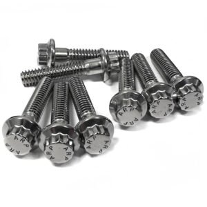
Brass CNC turned parts occupy a strange position in the machining world: they include both the easiest metal to cut and one of the hardest, and the two sit only a few percentage points apart in copper content. Free-cutting brass is the reference standard against which every other alloy’s machinability is measured — the definition of 100 %. Pure copper, chemically its close relative, rates around 20 %, tears rather than cuts, and welds itself to the tool. Treating “copper alloys” as one machining category is the root of most disappointing results in this material family. This guide covers the machinability spectrum and why it exists, tooling and process response for each end of it, thread production in copper alloys, stress corrosion cracking, reverse engineering legacy spare parts, achievable tolerances and finishes, and how to specify and source the work.
TL;DR — Key Takeaways
- Free-cutting brass C36000 is the machinability reference at 100 %; pure copper C11000 rates around 20 % — the widest spread inside any single metal family.
- Copper’s problem is ductility, not hardness: it forms a built-up edge on the tool and produces continuous chips that never break.
- Brass threads resist galling far better than stainless, which makes brass the forgiving choice for precision screws that are cycled repeatedly.
- Stress corrosion cracking (“season cracking”) splits high-zinc brass exposed to ammonia when residual machining stress is present — a stress-relief anneal prevents it.
- Reverse-engineering a worn spare part requires deciding between as-found and design-intent dimensions; measuring the worn surface and copying it reproduces the wear.

What Are Brass CNC Turned Parts?
Brass CNC turned parts start from a process that suits copper alloys unusually well. The lathe produces rotational geometry — diameters, faces, grooves, threads — around a single spindle axis, and most copper-alloy hardware is rotational by nature: fittings, terminals, bushings, spacers, valve components, and precision screws. Bar-fed turning also handles the volumes these parts come in, from single spare-part replacements to hundreds of thousands of electrical contacts.
Brass CNC turned parts are also called brass turned components, turned brass components, or brass machined parts, and they are specified across the electrical and telecommunications infrastructure, heating and ventilation (HVAC), electronics, gas, and renewable-energy markets — anywhere a conductive, corrosion-resistant, rotational part is needed. Brass contact and terminal parts in particular account for much of the demand for turned brass components.
| Part Family | Typical Alloy | Why Copper Alloy |
|---|---|---|
| Precision screws and studs | C36000 brass | Machinability, corrosion resistance, appearance |
| Electrical terminals and contacts | C11000 copper, brass | Electrical conductivity |
| Plumbing and pneumatic fittings | C36000, DZR brass | Corrosion resistance, sealing behaviour |
| Bushings and spacers | Brass, bronze | Bearing behaviour, non-galling |
| Valve components | Brass, naval brass | Corrosion, machinability |
| Heat-transfer components | C11000 copper | Thermal conductivity |
| Decorative hardware | C36000, C26000 | Appearance, polishing behaviour |
| Non-sparking tools and fittings | Brass | Safety in explosive atmospheres |
The two properties that keep copper alloys in service despite their cost — electrical and thermal conductivity — have no substitute in steel or aluminium at the same level. Where a part must conduct, copper alloys are chosen for physics rather than preference, and the machining challenges come with the territory.
KeyFix machines this family across its CNC production line, with representative work in the CNC parts portfolio and the wider product portfolio.
Why Do Copper Alloys Span the Entire Machinability Range?
Machinability ratings use free-cutting brass as the benchmark, which makes the spread within the copper family easy to read at a glance.
| Alloy | Designation | Machinability Rating | Behaviour on the Lathe |
|---|---|---|---|
| Free-cutting brass | C36000 | 100 % (reference) | Chips break cleanly; excellent finish |
| Leaded red brass | C83600 | 90 % | Very good; slight gumminess |
| Naval brass | C46400 | 70 % | Good; longer chips |
| Cartridge brass | C26000 | 30 % | Gummy; long stringy chips |
| Silicon bronze | C65500 | 30 % | Tough; work hardens |
| Aluminium bronze | C95400 | 20 % | Hard, abrasive; tool wear |
| Pure copper | C11000 | ~20 % | Tears and smears; built-up edge |
Two independent mechanisms create that spread. Lead content is the first: the roughly 3 % lead in C36000 exists as microscopic droplets dispersed through the alloy, which act as internal chip breakers and lubricants. The chip fractures at each lead inclusion instead of running continuously, and the lead smears a thin film ahead of the cutting edge. Remove the lead and the same brass becomes a different machining proposition entirely.
Ductility is the second. Copper in its pure form is extremely ductile — it deforms rather than shearing cleanly, so the cut produces a continuous chip that keeps growing, and material pressure-welds onto the tool face to form a built-up edge. That edge periodically breaks away, taking part of the machined surface with it, which is why poorly set up copper turning produces a torn, matte finish rather than a clean one.
💡 Engineer’s Note: Quote copper and brass parts as different jobs even when the geometry is identical. A part in C36000 and the same part in C11000 differ by a factor of three or more in cycle time, need different tooling, and carry different finish expectations. Buyers who quote “copper alloy” generically and then switch material mid-program are usually surprised by the repricing — the alloy, not the shape, drives the cost here.
How Does Tooling Respond to Each End of the Range?
The process answer to gummy material is the opposite of the answer for hard material, which is why experience with steel does not transfer directly.
| Parameter | Free-Cutting Brass (C36000) | Pure Copper / Gummy Alloys |
|---|---|---|
| Rake angle | Neutral to slightly negative | High positive — shears rather than pushes |
| Cutting edge | Standard sharp | Polished, very sharp — resists adhesion |
| Cutting speed | High | High — outruns built-up edge formation |
| Feed rate | Standard | Higher — thin chips weld more readily |
| Coolant | Optional | Flood, high volume — removes heat and chips |
| Chip control | Self-breaking | Chip breaker geometry required |
| Dwell at depth | Acceptable | Avoid — rubbing work-hardens the surface |
| Tool coating | Uncoated carbide common | Uncoated polished carbide or diamond-like |
The counter-intuitive item is feed rate. With steel, reducing feed usually improves finish. With copper, a very light cut rubs rather than cuts, burnishing the surface, generating heat, and accelerating built-up edge formation. A slightly heavier feed that produces a properly formed chip gives a better surface than a fine one that smears.
Sharpness matters more than hardness. A polished, keenly sharp edge gives the ductile material less surface to adhere to, so tooling for copper is chosen for edge quality rather than wear resistance — the opposite priority from machining hardened steel.
What Changes With Lead-Free Brass?
Lead-free brass grades have entered wide use, and their machining consequences are worth planning for regardless of what drives the switch.
| Grade Family | Chip Breaking | Tool Life | Cycle Time vs C36000 |
|---|---|---|---|
| C36000 (leaded) | Excellent | Longest | Baseline |
| Bismuth brass (C89833 etc.) | Good | Good | ~10–25 % longer |
| Silicon brass (C69300) | Fair | Moderate | ~25–50 % longer |
| Low-lead brass | Fair–good | Moderate | ~15–35 % longer |
Bismuth behaves similarly to lead in the microstructure, acting as a chip breaker, which is why bismuth grades machine closest to the leaded original. Silicon-based lead-free grades are tougher and work-harden more, so they demand sharper tooling, more coolant, and longer cycles.
The practical planning point is that a material substitution is a process change, not a drop-in. Cycle times rise, tool consumption rises, and a part quoted in C36000 will not hold the same price in a lead-free grade at the same volume. Raise the alloy question at quotation rather than after the first production run.
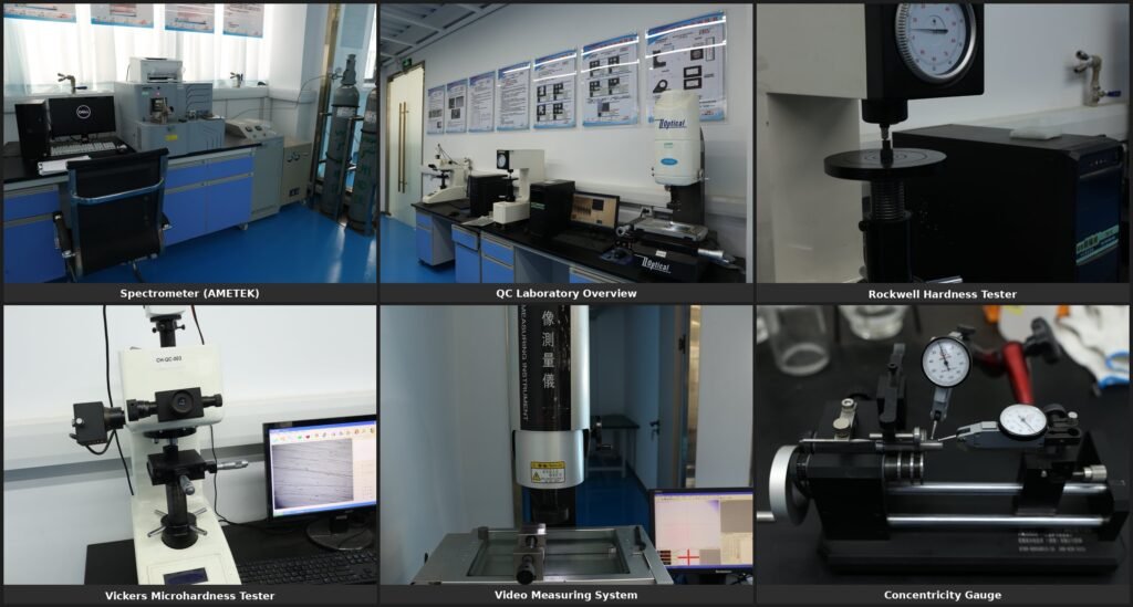
Incoming bar chemistry is confirmed on every lot by SPECTRO optical emission spectrometry through KeyFix’s raw material control process — the verification that separates a leaded free-cutting bar from a lead-free or off-spec grade before it reaches a spindle and changes the whole process window.
How Are Precision Screws Produced in Copper Alloys?
Brass has one significant advantage over stainless steel for threaded parts that see repeated assembly: it does not gall. Stainless-on-stainless threads cold-weld under pressure and seize; brass threads slide.
| Thread Property | Brass | Stainless Steel | Carbon Steel |
|---|---|---|---|
| Galling tendency | Very low | High | Low |
| Strength | Moderate | High | High |
| Repeated cycling | Excellent | Poor without lubricant | Good |
| Conductivity through thread | Yes | No | No |
| Corrosion resistance | Good | Excellent | Requires coating |
That non-galling behaviour makes brass the material of choice for adjustment screws, terminal screws, and instrument hardware that gets turned hundreds of times over a product’s life. The trade-off is strength: brass threads strip at far lower torque than steel, so brass precision screws belong in positions where fine control matters more than clamp load.
| Thread Method | Suits | Notes |
|---|---|---|
| Single-point turning | Prototypes, large or unusual threads | Full flexibility; slower |
| Thread rolling | Volume production | Stronger flank, no chips, faster |
| Die threading | Simple standard threads | Fast for short threads |
| Tapping (internal) | Internal threads | Brass taps cleanly |
Thread rolling works well on brass because the alloy forms readily — the rolled flank ends up smooth and work-hardened, improving both strength and thread feel. For volume production of brass precision screws, rolling on the 22 thread-rolling machines is both faster and produces a better thread than cutting. Where the part is a low-volume spare or carries an unusual pitch, single-point turning on the CNC line covers it.
📋 Spec Tip: On brass screws that will be adjusted repeatedly — set screws, terminal screws, calibration adjusters — specify a finer pitch than the standard coarse thread. Finer pitch gives more turns per millimetre of travel, which is the whole point of an adjustment screw, and spreads the load over more engaged threads in a material that strips easily.
What Is Stress Corrosion Cracking in Brass?
This failure mode catches people who have never encountered it, because the part passes every inspection, ships, and then splits weeks later on the shelf.
Brass containing more than roughly 15 % zinc is susceptible to stress corrosion cracking, historically called “season cracking” because British ammunition stored in Indian monsoon seasons cracked spontaneously. It requires three things simultaneously:
| Required Condition | Source in a Machined Part |
|---|---|
| Susceptible alloy | Brass above ~15 % zinc (most common brasses) |
| Residual tensile stress | Machining, cold forming, press-fitting, thread rolling |
| Specific corrosive agent | Ammonia or amine compounds — cleaning products, fertiliser, some adhesives |
Remove any one leg and the cracking does not occur. The controllable leg in manufacturing is residual stress: a low-temperature stress-relief anneal — typically a few hundred degrees Celsius for a short hold — relaxes machining stresses without significantly softening the part.
⚠️ Common Pitfall: Specifying a high-zinc brass for a component that will be press-fitted or heavily cold-worked and then stored or used near ammonia-based cleaning agents — common in food processing, laboratories, and agricultural equipment. The part passes production inspection with no defect, then cracks in storage or early service. Either specify a stress-relief anneal after machining, choose a lower-zinc alloy, or select a grade with inhibitors.
How Do You Reverse Engineer a Legacy Brass Spare Part?
Copper-alloy components are frequently ordered as replacements for equipment whose drawings are long gone, which turns the sample itself into the specification. That process has a trap worth naming.
| Step | What to Do | Why |
|---|---|---|
| 1. Identify the alloy | OES analysis of the sample | Appearance cannot distinguish brass grades |
| 2. Measure all features | Optical and contact measurement | Establishes the as-found geometry |
| 3. Separate wear from design | Identify which surfaces have worn | The critical judgement step |
| 4. Infer the design intent | Round to standard sizes, thread pitches, fits | Reconstructs the original drawing |
| 5. Confirm the mating parts | Measure or verify what it assembles to | Validates the inferred dimensions |
| 6. Produce a drawing | Document before cutting metal | Gives a repeatable specification |
Step three is where reverse engineering succeeds or fails. A worn bushing bore measured directly gives a dimension that is larger than the original by exactly the amount of wear — copy it and the replacement is born worn out. The same applies to thread flanks, sealing faces, and bearing journals.
The recovery method is inference: worn dimensions almost always sit near a standard value. A bore measuring 12.18 mm was almost certainly a Ø12 H7 bore; a thread that gauges loose was almost certainly a standard class before service. Measuring the unworn areas of the same part — a shoulder, an undercut, a face that never contacted anything — often reveals the original intent directly.
💡 Engineer’s Note: When commissioning a spare part from a sample, send the mating component too if one exists. A worn shaft plus its worn housing tells you far more than either alone, because the pair brackets the original fit from both sides. Where that is impossible, say explicitly on the enquiry whether you want the part copied as-found or reconstructed to design intent — these produce different parts, and the assumption is worth making visible.
Alloy identification, dimensional capture, and drawing reconstruction are documented under KeyFix’s inspection standards programme, using 2D video measuring, Shining3D 3D scanning for complex profiles, and Mitutoyo gauges for precision features.

What Tolerances and Finishes Are Achievable?
| Feature | Free-Cutting Brass | Pure Copper |
|---|---|---|
| Turned diameter tolerance | ±0.005 mm | ±0.01 mm |
| Bore tolerance | ±0.005 mm | ±0.01 mm |
| Surface finish, as-turned | Ra 0.4–0.8 μm | Ra 0.8–1.6 μm |
| Surface finish, polished | Ra 0.1 μm | Ra 0.2 μm |
| Thread class | 6g / 6H standard | 6g / 6H achievable |
| Concentricity, single chucking | 0.005 mm | 0.01 mm |
Brass takes a fine as-turned finish directly off the tool, which is one reason decorative hardware is made from it — a polished brass part starts from a better surface than most metals can reach without secondary operations. Copper needs more process attention to reach a comparable number, and smears if the setup is not right.
Thermal behaviour deserves a note on precision work: brass expands at roughly 20 μm/m·K against steel’s 12, so a brass part measured warm after machining reads larger than it will in service. On tight-tolerance parts, temperature-controlled measurement removes a source of apparent variation that is purely thermal.
Which Copper Alloy Fits an Electrical or Thermal Part?
Where a turned part exists to carry current or heat, the alloy choice is driven by conductivity rather than by machinability — and the two pull in opposite directions, because every alloying element that improves cutting also degrades conduction.
| Alloy | Electrical Conductivity (% IACS) | Machinability | Typical Electrical Use |
|---|---|---|---|
| C11000 (ETP copper) | 100 % | ~20 % | Busbar hardware, high-current terminals |
| C14500 (tellurium copper) | 90–95 % | 80–90 % | The engineering compromise |
| C18200 (chromium copper) | 80–85 % | 70 % | Welding electrodes, heat-loaded contacts |
| C36000 brass | 26 % | 100 % | Low-current terminals, earthing hardware |
| C26000 brass | 28 % | 30 % | Formed contacts |
The row worth knowing is tellurium copper C14500. It retains around 90 % of pure copper’s conductivity while machining four times more easily, because the tellurium forms chip-breaking inclusions in the same way lead does in brass. For a turned electrical contact that must conduct seriously and still be economical to produce in quantity, it usually beats both pure copper and brass.
💡 Engineer’s Note: Before specifying pure C11000 for a machined terminal, check whether the circuit truly needs the last 10 % of conductivity. Moving to tellurium copper typically cuts cycle time substantially and improves surface finish, at a conductivity cost that most connector and terminal applications never notice.
What Makes Deep Bores and Thin Walls Difficult?
Two geometries turn an ordinary copper-alloy job into a demanding one, and both appear constantly in fittings and terminal work.
| Challenge | Why Copper Alloys Make It Worse | Mitigation |
|---|---|---|
| Deep bores | Long chips pack into the hole and score the wall | Peck cycles, through-tool coolant, chip-breaking geometry |
| Thin walls | Low stiffness plus cutting pressure deflects the part | Light finishing passes, supportive workholding |
| Cross holes into a bore | Burrs raised inside a finished bore | Drill before final boring where the sequence allows |
| Long slender parts | Deflection under tool pressure | Guide bushing or tailstock support |
Thin-wall brass CNC turned parts deserve particular care because the material springs back less predictably than steel: a wall finished to size under cutting pressure relaxes when the tool leaves, and the bore reads slightly different afterwards. The practical answer is a light final pass that removes little material and therefore applies little force, which is why thin-wall copper-alloy parts carry longer cycle times than their geometry alone suggests.
How Are Brass CNC Turned Parts Produced and Verified?
| Step | What Happens | KeyFix Capability |
|---|---|---|
| Bar verification | Alloy and lead content by OES | SPECTRO (Germany), 100 % of heats |
| CNC turning | All diameters, faces, grooves in one chucking | 32 CNC machines incl. two 5-axis, ±0.005 mm |
| Live-tool features | Cross holes, flats, slots | Same setup — concentricity preserved |
| Thread production | Rolled at volume; single-point for specials | 22 thread-rolling machines |
| Internal threading | Tapped to class | 10 nut tapping machines |
| Stress relief | Low-temperature anneal where specified | Controlled-atmosphere furnaces |
| Deburr and clean | Chips removed from blind features | Controlled — critical on fittings |
| Finishing | Polished, plated, or as-machined | Controlled process lines |
| Verification | Diameters, threads, concentricity, finish | 2D video measuring + 3D scanning, Mitutoyo gauges, 100 % optical sorting |
Chip removal deserves its own line for copper alloys. The long continuous chips that pure copper and cartridge brass produce wrap around tooling and lodge in cross holes and internal features — a fitting shipped with a chip inside its bore fails on the assembly line rather than in inspection. Process detail sits on the technology overview, with near-net blanks for volume work from the cold forging line and delivered examples in the project case studies.
Need a quote on brass or copper turned parts? Send your drawing, or a sample for reverse engineering, to KeyFix — DFM review and quotation within 48 hours. Get a quote or email sales@keyfixpro.com.
What Should the Drawing Specify?
| Call-Out | What to Specify | Why It Matters |
|---|---|---|
| Alloy, precisely | C36000, C11000, C69300, etc. | Drives cycle time, cost, and finish |
| Lead status | Leaded or lead-free grade | Process window and pricing |
| Diameters + fit classes | Per feature, individually | Prevents blanket over-tolerancing |
| Thread + method | Size, class, rolled or cut | Strength and feel |
| Surface finish | Ra per functional surface | Brass reaches fine finishes as-turned |
| Stress relief | Required where SCC risk exists | Prevents delayed cracking |
| Concentricity | Between named features | Single-chucking requirement |
| Cleanliness | Chip-free internal features | Assembly-line failures start here |
| Finish | Polished, plated, or plain | Appearance and corrosion |
How Do You Qualify a Manufacturer?
| Audit Point | Minimum Requirement | KeyFix Status |
|---|---|---|
| Quality system | ISO 9001 minimum | IATF 16949 + ISO 9001 + ISO 14001 |
| Copper alloy experience | Both leaded and gummy grades | Documented across alloy range |
| Single-chucking capability | Multi-feature parts in one setup | 32 CNC machines with live tooling |
| Material verification | OES per bar lot | SPECTRO OES, 100 % of heats |
| Thread capability | Rolled and cut, internal and external | 22 rolling + 10 tapping machines |
| Reverse engineering | Alloy ID, 3D scanning, drawing creation | Full capability in-house |
| Dimensional control | Per-feature measurement documented | 2D video measuring + 3D scanning |
| Outgoing quality | Stated defect rate | <25 PPM at AQL 0.4 |
Copper alloy bar follows ASTM B16 and B187, with fits per ISO 286 and thread classes per ISO 965, under the quality system documented in KeyFix’s company background and applied across its machinery hardware programmes.
What Are the Logistics and Shipping Terms?
KEYFIX manufactures through its own production base in China, close to South China’s major export ports.
| Term | Detail |
|---|---|
| Manufacturing location | Own production base, South China |
| Standard shipping term | FCA at our production base |
| Sea freight term | FOB Shenzhen Yantian Port |
| Prototype lead time | 7–14 business days (air-expressed) |
| Production lead time | 4–6 weeks after sample approval |
Frequently Asked Questions
Why is pure copper harder to machine than brass?
Copper is extremely ductile, so it deforms rather than shearing cleanly. The chip runs continuously without breaking and material pressure-welds to the tool as a built-up edge, which periodically tears away and damages the surface. Free-cutting brass contains lead inclusions that break the chip and lubricate the cut, giving it a machinability rating of 100 % against copper’s 20 %.
Can I substitute lead-free brass without changing anything else?
No. Lead-free grades machine differently — cycle times rise by roughly 10–50 % depending on the grade, tool consumption increases, and the process window narrows. Treat an alloy substitution as a process change and re-quote it rather than assuming a drop-in replacement.
Are brass threads better than stainless for adjustment screws?
For repeated cycling, yes. Brass threads do not gall, while stainless-on-stainless threads cold-weld and seize under pressure. The trade-off is strength — brass strips at much lower torque — so brass suits fine-control positions rather than high-clamp-load joints.
What causes brass parts to crack in storage?
Stress corrosion cracking. High-zinc brass with residual machining stress, exposed to ammonia or amine compounds, cracks without any applied load. A low-temperature stress-relief anneal after machining removes the residual stress and prevents it.
Can you make a replacement part from a worn sample?
Yes, with one caveat worth agreeing in advance. A worn surface measured directly reproduces the wear in the new part, so worn dimensions are inferred back to design intent using unworn reference features and standard sizes. State whether you want the part copied as-found or reconstructed to the original specification.
What is the minimum order quantity?
CNC-turned copper alloy parts have no MOQ — from single prototypes and spare parts to bar-fed production, with price breaks at higher tiers. Contact sales@keyfixpro.com for quotations.
What shipping terms apply for international orders?
Standard shipping is FCA at our production base, with sea freight as FOB Shenzhen Yantian Port.
If your next programme needs brass CNC turned parts — precision screws, fittings, terminals, bushings, or a replacement machined from a worn sample — send your drawing or the part itself to KeyFix for a free DFM review and a quotation within 48 hours. Explore the CNC parts portfolio or contact KeyFix at sales@keyfixpro.com.
Author: KeyFix Engineering Team Published: July 11, 2026 Last Updated: October 21, 2026