EV motor housing bolts hold together parts that expand, vibrate, seal, and sometimes provide an electrical bonding path. Selecting a bolt by diameter and strength class alone leaves the joint underdefined. The useful starting point is the required clamp load throughout assembly, temperature changes, and service, together with the limits of the housing and its internal threads.
This guide focuses on housing flanges, end covers, and related structural joints. Stator retention and electrical terminals can have different load paths and acceptance criteria. Treat those interfaces separately rather than applying one torque table across the complete drive unit.
Key Takeaways
- Define each joint’s function before selecting the fastener: retention, sealing, alignment, or electrical bonding.
- Aluminum and steel can expand differently; heating can increase bolt tension in an ideal elastic joint, while settlement can reduce the retained preload.
- Internal thread capacity and bearing surface pressure can govern before bolt tensile capacity.
- A coating or lubricant change can alter clamp load at the same tightening torque.
- Validate the actual joint through temperature, vibration, and sealing requirements; a bolt certificate alone cannot validate the assembly.
What must EV motor housing bolts actually do?
EV motor housing bolts must maintain the joint’s specified mechanical and functional condition across its operating envelope. Different locations can retain covers, clamp flanges, support alignment, or provide a defined bonding path. Establish each function and load path first. The same bolt size does not make two housing joints equivalent in service.
Use this joint map before assigning a fastener family.
| Joint location | Primary function | Governing review |
|---|---|---|
| Housing perimeter flange | Retention and seal compression | Flange stiffness, pressure distribution, leakage |
| End cover | Retention and alignment support | Distortion, seating, bearing related tolerances |
| Structural mounting interface | Transfer mechanical loads | Slip, separation, fatigue, support stiffness |
| Stator related retention | Hold the specified internal component | Thermal field, retention load, insulation constraints |
| Dedicated bonding point | Maintain electrical continuity | Contact condition, corrosion, resistance verification |
The existing automotive fastener application framework provides a wider system view. Here, the purchasing unit is the joint: bolt, housing, internal thread, bearing surface, coating, seal, and assembly method. Requesting only a bag of dimensionally correct bolts omits several variables that determine performance.
Spec Tip: Mark sealing, structural, and bonding interfaces separately on the RFQ drawing. If the fastener also locates a component, state the locating feature and tolerance. Clearance threads should not be assumed to provide precision location.
How does thermal expansion change clamp load?
Thermal expansion changes preload when the bolt and clamped members would expand by different amounts if unconstrained. In an ideal elastic joint, members expanding more than the bolt increase bolt tension during heating. Actual EV motor housing bolts also experience temperature gradients, settlement, material relaxation, and changing stiffness, so the retained preload requires a broader assessment.
The PPPL Handbook for Bolted Joint Design treats thermal expansion mismatch as a source of preload change. Use the actual material data and load path lengths for the application. A single temperature at the housing exterior may not represent the bolt or every clamped layer.
For a first elastic screening calculation, differential free expansion equals clamped length multiplied by the difference in thermal expansion coefficients and temperature change. This simplified expression assumes the bolt and a uniform member stack share the same temperature change. It estimates displacement, not an approved preload or tightening torque.
These are assumed inputs for a worked example, not material certification values or a KEYFIX design specification.
| Illustrative input | Assumed value | Meaning |
|---|---|---|
| Clamped length | 50 mm | Simplified common expansion length |
| Member expansion coefficient | 23 × 10⁻⁶/K | Assumed value for the example |
| Bolt expansion coefficient | 12 × 10⁻⁶/K | Assumed value for the example |
| Common temperature rise | 100 K | Uniform rise assumed for both |
| Differential free expansion | 0.055 mm | 50 × (23 − 12) × 10⁻⁶ × 100 |
The resulting 0.055 mm cannot be treated as bolt extension directly. The bolt stretches while the compressed members deform, so the effective stiffness is the series combination of bolt stiffness and member stiffness. The elastic preload change equals differential free expansion multiplied by that effective stiffness. Flange flexibility and the internally threaded region affect the result.
For illustration only, assume bolt stiffness is 100 kN/mm and member stiffness is 200 kN/mm. The effective stiffness is 100 × 200 / (100 + 200), or about 66.7 kN/mm. Multiplying by 0.055 mm gives an estimated increase of 3.67 kN. These assumed inputs demonstrate the calculation; actual bolt stiffness and member stiffness must be established for the joint.
The elastic calculation is reversible only under its assumptions. If local bearing surfaces embed, aluminum relaxes, a gasket compresses further, or a thread region deforms, cooling may not restore the original preload. Review maximum hot bolt load and minimum retained cold clamp load as separate limits. Both matter when choosing EV motor housing bolts.
How should strength, geometry, and aluminum threads be selected?
Select bolt strength and geometry against the weakest relevant joint limit, including internal thread stripping, bearing pressure, separation, and fatigue. A stronger bolt does not strengthen the aluminum boss around it. Thread engagement, usable hole depth, head bearing area, and flange stiffness need to be checked with actual material properties and tolerances.
Start with the required clamp load window. Its lower boundary comes from the functions that need contact, such as preventing separation or maintaining seal compression. Its upper boundary comes from allowable bolt load and the housing’s local capacity. Assembly scatter and service changes must fit between those boundaries with the design’s required margin.
This selection matrix identifies the information needed before approving a bolt upgrade.
| Design variable | Potential benefit | Limit to check |
|---|---|---|
| Higher strength class | Increased bolt load capacity | Housing thread and bearing capacity |
| Larger bearing face | Lower nominal contact pressure | Seating geometry and flange access |
| Longer engagement | More potentially load carrying thread | Actual boss material and usable depth |
| More elastic grip | Reduced sensitivity to a given settlement | Package space, fatigue, and stiffness |
| Inserted thread | Defined mating thread system | Insert retention, installation, repair policy |
| Thread forming approach | Alternative fastening route in suitable holes | Hole geometry and validated installation window |
Avoid a universal engagement rule such as a fixed multiple of diameter for every cast alloy. Local casting quality, thread form, boss dimensions, and the load requirement influence the outcome. State whether engagement means full effective threads or the distance from the entry face to the end of the bolt; those are not necessarily equal.
Blind holes need particular attention. Account for entry chamfers, incomplete internal threads, tap runout, bolt tip geometry, trapped debris, and coating thickness. A bolt that bottoms can register torque without producing the intended clamp load. A drawing should distinguish drilled depth, tapped depth, and usable engagement at tolerance extremes.
Review the thread forming screw guide for die cast aluminum when that fastening route is under consideration. Thread forming screws require their own installation validation; they cannot inherit the tightening assessment of a conventional machine screw simply because the nominal diameter matches.
How do coatings and friction affect tightening?
Coatings, topcoats, lubricants, and mating surfaces influence how tightening torque converts into clamp load. A torque value is therefore incomplete without the tested surface condition. When specifying EV motor housing bolts, define the full finish and assembly state, then validate the clamp load distribution rather than treating coating color as an engineering parameter.
The simplified screening relation is torque equals nut factor multiplied by clamp load and nominal diameter. The nut factor is an empirical assembly parameter, not the same quantity as a coefficient of friction. Use consistent units, and do not transfer a factor from an unrelated joint into a production torque specification.
This sensitivity example uses assumed factors and is not a recommended tightening setting.
| Illustrative condition | Torque | Nominal diameter | Assumed nut factor | Calculated clamp load |
|---|---|---|---|---|
| Example A | 8 N·m | 0.006 m | 0.20 | About 6.67 kN |
| Example B | 8 N·m | 0.006 m | 0.16 | About 8.33 kN |
The arithmetic shows why changing friction at a fixed torque can change bolt load. It does not predict the scatter of a real assembly. Prevailing torque, thread forming, tool dynamics, surface damage, and nonstandard geometry can require a more specific model and test method.
ISO 16047:2005, including Amendment 1:2012, addresses torque/clamp force testing within its stated scope. Its scope excludes screws that form their own mating thread and fasteners with additional self locking features. Those exclusions matter when a housing program uses patched screws, prevailing torque features, or thread forming designs.
The finish specification should separate these functions.
| Finish requirement | What to define | Validation question |
|---|---|---|
| Corrosion protection | Complete system and exposure requirement | Does protection survive the specified environment? |
| Tightening behavior | Lubrication and mating surface condition | Is the clamp load window achievable? |
| Thread fit | Coating allowance and final gauging | Will final coated threads assemble correctly? |
| Electrical contact | Conductive contact area or masking | Is the intended bonding path maintained? |
| Hydrogen risk | Material condition and complete process route | Are applicable prevention controls established? |
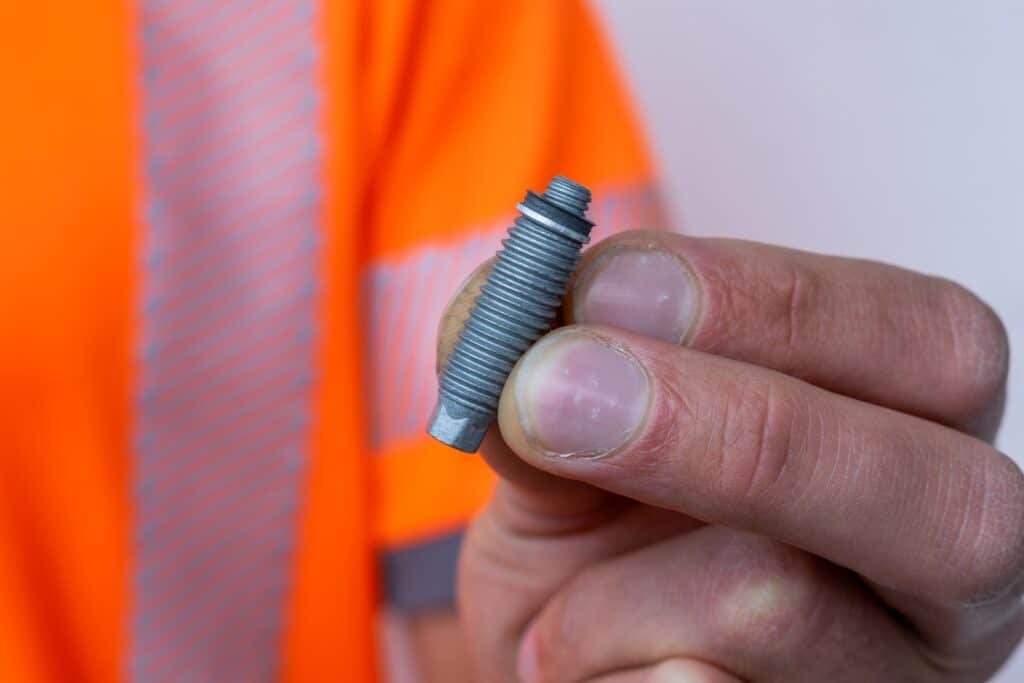
Specify zinc flake by the complete approved system when it suits the application. ISO 10683:2018 covers non electrolytically applied zinc flake coating systems. The standard’s scope does not make every topcoat electrically conductive or every friction behavior interchangeable. The joint still needs its agreed acceptance criteria.
How can vibration and preload loss be controlled?
Control vibration related loosening by maintaining the required clamp load, limiting joint movement, and validating any locking feature in the actual assembly. Settlement and rotational self loosening are different mechanisms. A locking feature may resist rotation without restoring clamp load lost through embedding, gasket compression, relaxation, or local yielding of the housing.
Ask what changed when a bolt is found loose. A backed out screw suggests rotation, while reduced clamp load with little rotation may point toward settlement or relaxation. Tool records, witness marks, dimensional inspection, and a suitable validation test help distinguish the mechanisms. Do not treat residual breakaway torque as a direct measurement of retained preload.
This failure map links the observation to a useful review.
| Observation | Mechanism to investigate | Design or process review |
|---|---|---|
| Rotation or backing out | Relative movement and self loosening | Clamp load, interface slip, locking strategy |
| Clamp loss without clear rotation | Settlement or material relaxation | Bearing surfaces, gasket, local pressure |
| Cracking near first loaded thread | Fatigue, overload, or interacting damage | Load path, preload, geometry, material |
| Housing boss damage | Thread or local material failure | Engagement, casting, installation limit |
| Distorted cover | Uneven loading or flexible flange | Bolt pattern, sequence, flange stiffness |
Typical Scenario: An aluminum end cover passes the initial leak check but loses sealing performance after temperature and vibration exposure. The first review should compare retained clamp load, flange flatness, seal compression, and local seating. Increasing installation torque without that evidence may overload the housing while leaving the relaxation mechanism unresolved.
For EV motor housing bolts, compare candidate locking approaches using the same joint configuration and service sequence. If a chemical locking feature is proposed, define cleaning, curing, service temperature, and removal requirements with the material supplier. If a mechanical feature is proposed, verify mating surface effects and assembly compatibility. Neither category is an automatic substitute for joint validation.
How should sealing, bonding, and insulation be separated?
Sealing, electrical bonding, and electrical insulation need distinct interface requirements because their preferred surface conditions can conflict. A seal needs controlled compression; a bonding point needs a verified conductive path; an insulating interface needs controlled separation. Do not assign all three functions to a coated bolt without defining the complete assembly and test conditions.
For a sealed housing flange, document the gasket or sealant system, groove or bead geometry, surface condition, and tightening sequence. Bolt spacing and flange stiffness affect how clamp load reaches the seal between fasteners. Passing a bolt dimensional check does not establish adequate compression around the entire perimeter.
Separate the functional acceptance requirements as follows.
| Function | Interface definition | Evidence after conditioning |
|---|---|---|
| Sealing | Seal material, geometry, surface, compression | Agreed leak or ingress test |
| Electrical bonding | Contact faces, coating treatment, path | Specified electrical continuity assessment |
| Electrical insulation | Barriers, clearances, insulating materials | Program specific insulation verification |
| Serviceability | Removal and replacement procedure | Demonstrated maintenance process |
The automotive grounding stud guide covers dedicated bonding interfaces. Keep that function visible in the housing drawing instead of relying on incidental contact through a thread. An apparently metallic finish is not proof of an electrically acceptable surface, particularly when sealers and topcoats are present.
Insulation requirements near stator windings and terminals belong to the electrical design and the drive unit’s verification plan. Do not claim that an insulating washer or coating makes the whole housing electrically safe. The assembly’s complete current paths, fault conditions, and material behavior require program level review.
For EV motor housing bolts near a sealed or electrically defined interface, control substitutions across the full stack. A replacement washer can change compression, friction, corrosion pairing, or contact resistance. Treat the washer and finish as specified parts of the assembly rather than optional purchasing accessories.
What should manufacturing and inspection control?
Manufacturing and inspection should control the characteristics that influence the actual housing joint: thread fit, bearing geometry, material condition, coating, and traceability. Choose a process against geometry and volume rather than claiming one process is always superior. Critical dimensions and verification methods must be agreed before production, including any special mechanical tests.
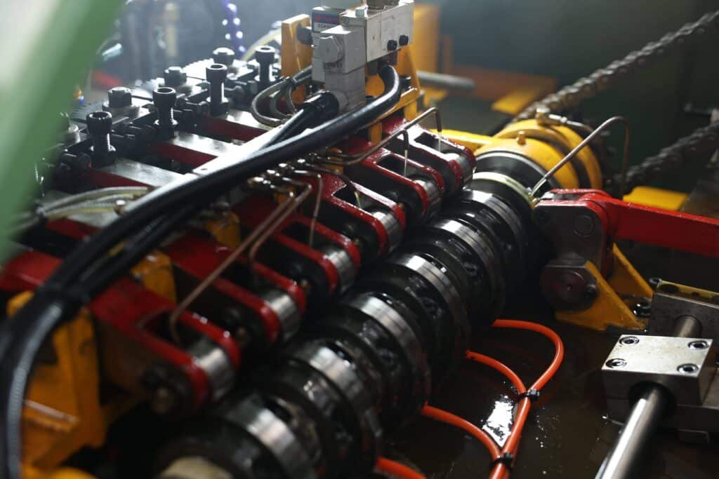
KEYFIX supports cold heading, thread rolling, CNC turning, and five axis machining. Its equipment includes 25 cold heading machines and 32 CNC machines, including two YCM NFX 380A five axis centers. These capabilities support process selection for custom fasteners and machined parts; they do not replace a part specific DFM review.
Use this control matrix to connect the drawing to inspection evidence.
| Characteristic | Why it affects the joint | Evidence to define |
|---|---|---|
| Final thread size and fit | Assembly and load transfer | Final condition go/no-go inspection |
| Bearing face geometry | Seating and local contact pressure | Dimensional and surface requirements |
| Material and hardness | Strength and process response | Material identification and hardness record |
| Coating and lubrication | Corrosion and tightening behavior | Approved system and lot documentation |
| Critical lengths | Engagement and bottoming clearance | Drawing linked dimensional results |
| Traceability | Investigation and change control | Links across material, finish, and inspection |
KEYFIX inspection equipment includes SPECTRO OES material analysis, two dimensional video measurement, and Rockwell and Vickers hardness testing. Tensile, proof load, and torque/clamp force verification are arranged through third-party testing laboratories when required. The quotation should state which inspections are routine and which additional tests form part of the agreed scope.
For EV motor housing bolts, the control plan should specify when the final condition is inspected. A thread that passes before coating can behave differently after coating. A mechanical test performed on an uncoated sample does not characterize the friction of the finished production lot. Align the sample condition with the question the test is intended to answer.
How should the assembled joint be validated?
Validate the assembled joint using the actual housing material, fastener finish, seal, mating surfaces, and assembly procedure. Measure the functional requirements after the relevant conditioning sequence. Individual tests on bolts provide useful inputs, but they cannot establish how a flexible flange, aluminum threads, gasket, and temperature field behave together throughout service.
Build the validation plan around a lower and upper clamp load boundary. Assess the lowest expected retained load against separation, slip, and sealing needs. Assess the highest installation or thermal load against bolt and housing limits. Include the planned assembly variation rather than validating only one carefully selected nominal sample.
A practical validation sequence can follow these steps.
- Confirm the drawing revision and identify every component in the joint stack.
- Establish baseline tightening behavior using representative finished parts.
- Record the selected preload or clamp load evidence and initial functional results.
- Apply the specified thermal, vibration, and environmental conditioning sequence.
- Recheck the relevant mechanical, sealing, and electrical functions.
- Inspect damage and approve the resulting acceptance window and control plan.
The NASA thermal load analysis for preloaded joints provides a technical reference for thermal mismatch modeling. Use the motor program’s actual requirements for acceptance.
Temperature cycling deserves measurements after returning to the reference condition as well as at relevant operating conditions. A hot elastic increase in bolt load can coexist with permanent settlement that reduces the later cold load. Looking only at the hot condition can therefore miss the retained clamp load problem.
Repeat the relevant validation when a meaningful variable changes: alloy, boss geometry, coating, lubricant, locking feature, seal, supplier route, or assembly strategy. A purchasing change that leaves the nominal thread size untouched can still alter joint behavior. Keep those change triggers in the approved control plan for EV motor housing bolts.
What belongs in the drawing and RFQ?
The drawing and RFQ should define the fastener, complete mating stack, operating conditions, assembly method, and acceptance evidence. A clear requirement allows process and cost tradeoffs to be reviewed before tooling. For EV motor housing bolts, include minimum retained function and maximum allowable loading rather than supplying only a nominal torque and diameter.
The following RFQ package supports a technical quotation.
| RFQ field | Required detail |
|---|---|
| Geometry | Drawing, model, revision, threads, bearing face, grip and engagement |
| Housing | Alloy, condition, boss geometry, tapped and drilled depths |
| Material | Bolt grade, mechanical requirements, approved alternatives |
| Finish | Complete coating, topcoat, lubricant, electrical requirements |
| Service | Temperature range, gradients, vibration, environment, seal requirements |
| Assembly | Tool strategy, tightening sequence, reuse and maintenance policy |
| Verification | Part inspection, joint validation, sample condition, reporting |
| Purchasing | Annual usage, batch size, traceability and change approval |
KEYFIX offers CNC machined and turned parts with no MOQ. Cold headed production is typically 5,000–10,000 pieces per size. Prototypes and samples are typically 7–14 business days; production is typically 4–6 weeks after sample approval. New cold heading tooling and special coatings are scheduled at quotation, depending on part complexity and the approved requirements.
Send the drawing and application details through the KEYFIX contact page. Quotation and DFM feedback are usually available within 48 hours of receiving a complete drawing. State any specialized joint testing at the start so the quotation includes the correct sample quantities, verification scope, and reporting responsibilities.
Frequently Asked Questions
Is there one standard tightening torque for an aluminum motor housing?
No. The torque depends on the fastener, finish, lubrication, housing threads, bearing surfaces, and required clamp load. Establish the production setting through the approved joint design and representative assembly testing.
Can a higher strength bolt solve stripped housing threads?
Not by itself. Increasing bolt capacity does not increase the capacity of the internal aluminum thread. Review engagement, boss geometry, material condition, and the assembly load limit.
Does aluminum expansion always make the bolts loose when hot?
No. In an ideal elastic joint, a member stack expanding more than the bolt can increase bolt tension on heating. Permanent settlement, relaxation, and temperature gradients can change the actual result.
Can housing bolts be reused after service?
Follow the program’s approved service procedure. Reuse depends on the bolt design, loading history, locking feature, coating condition, and inspection requirements; do not assume that an undamaged appearance is sufficient.
Can a salt spray requirement replace electrical bonding verification?
No. Corrosion performance and electrical continuity are different functional requirements. A bonding interface needs the specified electrical assessment after the relevant environmental conditioning.
Does KEYFIX perform torque/clamp force testing internally?
No. Torque/clamp force and other specified mechanical tests are arranged through third-party testing laboratories. The test method, sample condition, acceptance criteria, and reporting scope are agreed for the project.