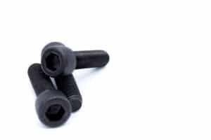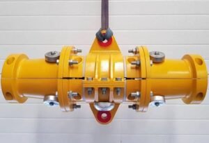
Captive panel screws keep service hardware attached to a removable cover after the mating thread is disengaged. That simple function becomes harder when a panel is painted, holes do not align perfectly, or technicians repeatedly open the enclosure. A useful specification separates screw retention, panel attachment, and thread engagement instead of treating them as one feature.
Key Takeaways
- Captive retention keeps a released screw with the panel; it does not automatically prevent loosening when the joint is tightened.
- Self-clinching and flare mounting describe attachment methods. Floating describes an alignment capability that can accompany a mounting arrangement.
- Retraction travel, available float, and useful thread engagement are different dimensions.
- Installation and service testing need the actual panel material, finish, and mating hardware.
- Specify the assembly drawing and acceptance evidence before selecting a replacement by appearance.
How do captive panel screws retain a removable cover?
Captive panel screws use a retaining arrangement that allows the screw to disengage from its mating thread while remaining attached to the removable panel. The screw, panel retainer, and mating threaded component perform separate jobs. Define those interfaces individually so the assembly can open, close, and maintain its required clamping function.
Southco’s captive screw overview describes the hardware loss prevention function. The engineering distinction is between keeping a loose screw with a cover and keeping a tightened joint secure. A captive screw can still lose preload if the joint settles or the locking strategy is inadequate.
This interface map prevents those functions from being confused.
| Interface | Required function | Evidence to define |
|---|---|---|
| Screw to retainer | Remain captive after release | Retention and full retraction check |
| Retainer to panel | Stay attached during handling and service | Installation and retention assessment |
| Screw to mating thread | Start correctly and produce required clamping | Engagement and tightening validation |
| Panel to frame | Close with the required position and fit | Finished assembly inspection |

A spring can help retract the screw, but spring action alone does not define the complete retention system. A retaining ring, shoulder, or other specified geometry must be evaluated in its actual assembly. Do not approve a component substitution only because the head and thread size look familiar.
Which mounting and alignment features should be compared?
Compare panel attachment and alignment as separate design choices. A self-clinching retainer is attached through local panel material flow, while a flare-mounted retainer uses its specified forming arrangement. Floating hardware allows defined movement for alignment. A ring retaining the screw addresses another interface, so these descriptions are not always mutually exclusive alternatives.
PennEngineering’s engineering guide illustrates self-clinching, flare-mounted, and floating product configurations. Their dimensions and installation limits are product specific. Use the selected design’s controlled information rather than transferring a hole size or hardness limit from a visually similar part.
The comparison below identifies the drawing questions behind each feature.
| Feature | Main design question | Item to specify |
|---|---|---|
| Self-clinching attachment | Can the panel form the retaining interlock? | Material, hardness, thickness, hole, tooling |
| Flare-mounted attachment | Can the retainer be formed and supported correctly? | Formed geometry and installation access |
| Ring or washer retention | Will the screw remain captured through travel? | Groove, retaining element, assembly sequence |
| Floating arrangement | Can available movement absorb misalignment? | Direction, usable travel, limiting surfaces |
| Spring retraction | Will the screw clear the mating component? | Retracted position and service clearance |
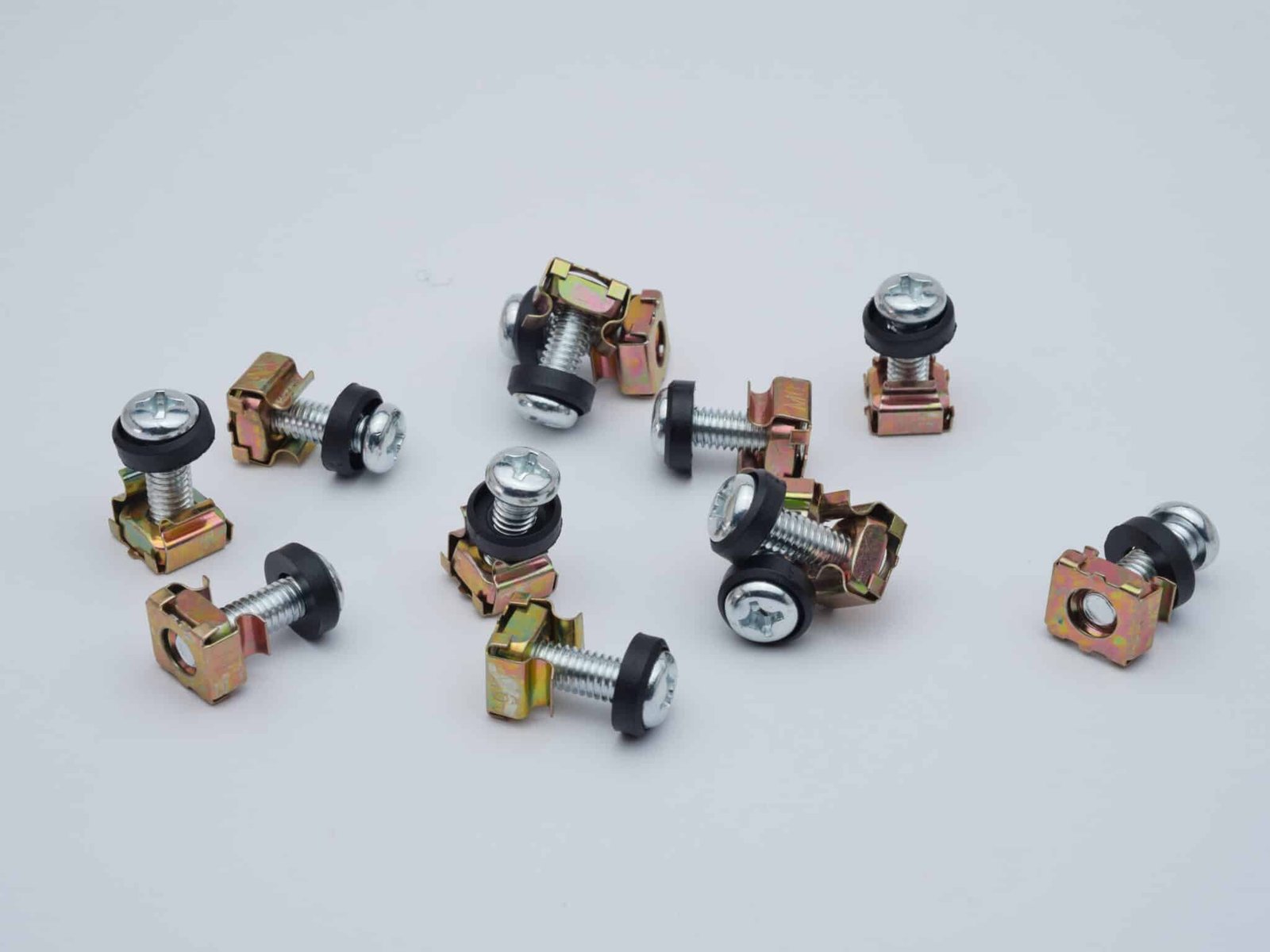
Common Pitfall: A cage nut captures the mating nut in a rack opening; it does not by itself keep a removed screw attached to a service panel. Check screw retention separately from nut retention. A screw-and-cage-nut assembly should not be specified as a captive panel screw solely because the nut remains in the frame.
Spec Tip: Mark the fixed interface and the permitted moving interface on a section drawing. A statement such as “floating captive screw” leaves room for misunderstanding unless the allowable movement and installation method are also defined.
For surrounding sheet metal hardware, see the self-clinching fastener selection guide. That guide concerns mating hardware and panel installation; the captive screw still needs its own retention and travel requirements.
What panel conditions determine installation quality?
Panel material, local thickness, hardness, hole condition, coating, and tool access determine whether the selected retainer can be installed correctly. Inspect the condition at the actual mounting location. A nominal sheet thickness on a purchasing specification does not describe burrs, paint buildup, nearby bends, or local distortion in the finished panel.
Southco’s self-clinching installation guidance explains the material flow that retains a clinched component and the need for a suitable prepared hole. The practical control is to connect the fastener drawing to the panel drawing and the approved installation process.
Use this checklist before releasing the panel and fastener combination.
| Panel condition | Possible effect | Control to agree |
|---|---|---|
| Insufficient local thickness | Incomplete attachment or poor seating | Thickness at the mounting location |
| Material or hardness change | Different forming and retention behavior | Approved panel condition |
| Burr or unsuitable hole | Inconsistent seating and alignment | Hole preparation and orientation |
| Paint or other finish | Changed fit and contact surfaces | Installation before or after finishing |
| Nearby bend or edge | Restricted support and local distortion | Tool clearance and panel geometry |
Evaluate the final manufacturing sequence. Installing before painting and installing into a finished panel are different process conditions. Specify which surfaces must remain clear, how moving parts are protected, and how the finished assembly is checked for free travel.
The precision stamping guide provides related panel design context. Retention force and any installation load must come from the selected assembly’s requirements and validation, not from a generic fastener table.
How much float, retraction, and engagement are needed?
Available float must cover the defined alignment error while leaving a usable thread starting position. Retraction must let the panel open without the screw catching the frame, and engagement must remain adequate when closed. Check these three conditions at tolerance extremes; a large movement value in one direction cannot compensate for another missing clearance.
Distinguish one-sided movement from total travel across both directions. The following example assumes symmetric lateral movement and aligned worst-case errors along one axis. The values demonstrate tolerance bookkeeping only; they are not dimensions recommended for a particular captive screw.
| Illustrative input | Assumed value | Interpretation |
|---|---|---|
| Panel hole position contribution | ±0.15 mm | One error contribution |
| Mating hole position contribution | ±0.20 mm | Second error contribution |
| Worst-case relative offset | 0.35 mm | Sum of the two assumed magnitudes |
| Defined total symmetric float | 0.80 mm | Equivalent to 0.40 mm each way |
| Remaining one-sided allowance | 0.05 mm | Before other effects are included |
That 0.05 mm is not a design approval margin. Panel distortion, finish, component tilt, temperature, and the full positional tolerance definition may consume additional movement. Confirm the supplier’s definition of float and analyze the actual geometry in both lateral directions.
Axial travel needs a separate section view. Show the retracted screw tip, the panel opening path, the fully seated position, and usable engagement. A long screw that reaches the mating thread can still bottom in a blind hole or obstruct removal when released.
Why do captive screws jam, spin, or fall out?
Captive screws can jam when alignment or travel is inadequate, spin when panel attachment is damaged, or escape when the retaining arrangement is incorrect. Determine which interface failed before changing the screw. Excess installation force or tightening torque can damage another component without correcting the original retention or fit problem.
This symptom map helps define an investigation.
| Observation | Interface to investigate | Useful evidence |
|---|---|---|
| Screw will not start | Screw and mating thread alignment | Float, thread condition, panel fit |
| Retainer rotates in panel | Panel attachment | Hole, material, installation condition |
| Screw falls free when released | Screw retention | Ring, shoulder, groove, travel limits |
| Panel catches during opening | Retraction and opening path | Retracted tip position and clearances |
| Joint loosens while closed | Clamped connection | Preload, settlement, locking strategy |
Typical Scenario: A service cover closes easily before finishing but binds after painting. Review finish buildup, retainer movement, panel position, and thread starting clearance using finished samples. Substituting a smaller screw without that review may introduce a new engagement problem.
Captive retention is also separate from grounding and sealing. If the enclosure needs either function, define the contact surfaces or seal requirements explicitly. The custom PCB standoff guide discusses another enclosure interface where stack height and surrounding components affect assembly.
How should the finished assembly be verified?
Verify retention, free movement, thread starting, closure, and repeated service operation on representative finished assemblies. Component dimensions alone do not establish those functions. Agree the test conditions, sample condition, and acceptance criteria before production, including any required mechanical retention tests and the method for reporting failures or damage.
The verification plan should connect each requirement to observable evidence.
| Requirement | Verification activity | Record |
|---|---|---|
| Panel attachment | Inspect seating and perform specified retention assessment | Installation condition and result |
| Screw captivity | Exercise full permitted travel and handling | Retained or released condition |
| Alignment | Start threads at relevant tolerance conditions | Starting behavior and interference |
| Closed joint | Apply the approved tightening procedure | Seating and functional result |
| Service life | Repeat the specified opening and closing sequence | Wear, damage, and function afterward |
Set the service sequence from the application rather than choosing an unsupported universal cycle count. Include the actual tool, access direction, and replacement procedure. If the retainer is damaged during maintenance, the service instruction should state whether it can be replaced and what inspection is required afterward.
What should a custom captive screw RFQ contain?
A custom RFQ should include the complete assembly drawing, individual component geometry, panel condition, mating thread, travel requirements, and acceptance evidence. This lets the screw and retainer be reviewed against their actual functions. Include service access and production volume so manufacturing choices can be compared without assuming that every component uses the same process.
Use this RFQ checklist for captive panel screws.
| RFQ field | Required detail |
|---|---|
| Component definition | Assembly and part drawings, revision, material |
| Panel and frame | Material, thickness, hardness, finish, mounting hole |
| Threaded connection | Thread, mating hardware, usable engagement |
| Retention and motion | Attachment method, captive feature, float, retraction |
| Service conditions | Access, tool, opening path, replacement policy |
| Acceptance | Inspection, retention tests, service sequence, traceability |
| Purchasing | Prototype quantity, batch quantity, annual usage |
KEYFIX supports custom fastener components through cold heading, thread rolling, and CNC turning. Send component and assembly drawings for a part-specific DFM review. Required pull-out, push-out, and other mechanical tests are arranged through third-party testing laboratories when specified.

See the CNC production overview for machining capabilities. Quotation and DFM feedback are usually available within 48 hours of receiving a complete drawing. Send the drawing package through the contact page and identify the required verification scope with the inquiry.
Frequently Asked Questions
Are captive screws also locking screws?
Not necessarily. Captive retention keeps a disengaged screw attached to the panel. Resistance to loosening while tightened requires a separate joint design and, where needed, a validated locking strategy.
Can a floating screw correct any misalignment?
No. Float has a defined direction and range, and the assembled parts must still allow the thread to start. Compare usable movement with the complete tolerance stack and surrounding clearances.
Can the same retainer be used in steel and aluminum panels?
Do not assume interchangeability. Review the selected retainer’s requirements for material, hardness, thickness, hole preparation, and installation. Validate the actual finished combination.
Is a spring required for every captive panel screw?
No. Retention and spring retraction are separate functions. Select the arrangement according to the required opening clearance, handling, and service behavior.
Should the mounting hole be drilled larger if the screw binds?
Only through an approved design change. Enlarging a hole can damage panel attachment or alter alignment. Investigate the affected interface and check the finished panel and hardware first.
What should accompany a request for custom components?
Provide the assembly drawing, component drawings, panel condition, mating thread, travel requirements, quantities, and verification scope. Identify any special mechanical or service testing when requesting the quotation.