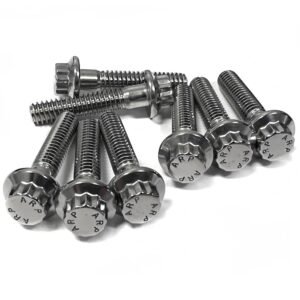
Self-clinching nuts for electronics enclosures give thin sheet metal a strong, permanent, flush-sided thread without welding, tapping or loose hardware. They are the standard way to mount PCBs, brackets, covers and grounding points in control cabinets, server chassis, inverter housings, telecom boxes and instrument cases. This guide explains how clinch hardware works, how to match it to the panel, and what to put on the drawing so that parts install correctly the first time.
Key Takeaways
- A self-clinching fastener works by displacing panel material into an undercut on the fastener, so the fastener must always be harder than the panel. Panel hardness is the first thing to check.
- Typical maximum panel hardness ranges from about HRB 50 for aluminum fasteners to about HRB 80 for hardened steel fasteners and up to about HRB 88–92 for hardened stainless types, according to PennEngineering’s published engineering guide.
- Annealed 304 stainless sheet is HRB 80 or harder, so standard 300-series stainless clinch nuts will not clinch into it. Stainless panels need hardened stainless fasteners.
- Hole size, edge distance, sheet thickness and press setup decide installation quality. Clinch hardware must be pressed in with a parallel squeeze, never hammered.
- Push-out and torque-out values belong on the drawing, measured in the actual panel material, because the panel controls the result as much as the fastener does.

What is a self-clinching nut and how does it work?
A self-clinching nut is a hardened threaded fastener with a knurled or serrated collar and an undercut groove. When it is pressed into a correctly sized hole in a ductile sheet, the collar displaces panel material into the undercut. The knurl resists rotation (torque-out) and the cold-flowed material locked in the undercut resists push-out. The result is a permanent thread that sits flush on the reverse side of the panel.
The installation is a cold-forming operation on the panel, not on the fastener. Three conditions must be met:
- The fastener is harder than the panel, so the panel deforms and the fastener does not.
- The panel is ductile enough to flow into the undercut without cracking.
- The installation force is applied squarely, with the head of the fastener flush to the panel surface.
Because no heat is used, clinch hardware does not burn off coatings, distort thin panels or create weld spatter near electronics. That is why it dominates sheet-metal enclosures in electronics, where panels are often 0.8–3 mm thick, pre-finished and cosmetically visible.
Which self-clinching fastener types are used in electronics enclosures?
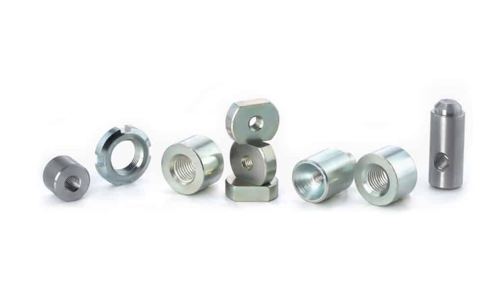
Electronics enclosures use six main clinch fastener families: nuts for threaded holes, studs for external threads, standoffs for spacing PCBs and panels, floating nuts for tolerance compensation, blind (closed-end) nuts for sealed or cosmetic sides, and self-locking nuts for vibration. Each solves a specific assembly problem.
| Type | What it provides | Typical use in an enclosure | Design note |
|---|---|---|---|
| Clinch nut | Internal thread flush on the reverse side | Covers, brackets, rails, DIN-rail mounts | Most common type; check minimum sheet thickness |
| Clinch stud | External thread, flush head | Grounding points, hinge and component mounting | Load should press the head against the sheet |
| Clinch standoff | Threaded or through spacer | PCB mounting, panel stacking | Length tolerance controls PCB height |
| Floating nut | Nut that moves inside a retainer | Mating parts with positional tolerance | Absorbs misalignment between panels |
| Blind nut | Closed end | Visible side or where screw tips must be hidden | Protects components behind the panel |
| Self-locking nut | Prevailing-torque thread | Fans, transformers, vibration-loaded parts | Specify prevailing torque and reuse cycles |
Engineer’s Note: Load direction matters. A clinch nut should be loaded so that the screw pulls the nut into the panel, not out of it. A clinch stud should be tightened so that its head is pressed against the sheet. Designs that load the fastener against its own push-out direction rely only on the clinch, which is the weakest path.
Thread sizes in enclosures are usually small: M2.5 to M6 for most electronics, with M8 and larger for heavier cabinet structures. For PCB mounting, standoffs are often combined with short screws and, in plastic sub-assemblies, with brass threaded inserts for plastic.
How does panel hardness affect self-clinching fasteners?
Panel hardness decides whether a clinch fastener will install at all. The fastener must be harder than the panel; if the panel is too hard, the panel will not flow into the undercut, and the fastener will push out or spin under low load. Check the panel material and temper against the fastener’s rated maximum panel hardness before choosing a part.
The values below are from PennEngineering’s engineering guide on fasteners for stainless steel panels. They are a useful starting point; always confirm with the data sheet of the actual fastener and a test on your panel.
| Fastener material | Approximate maximum panel hardness |
|---|---|
| Aluminum | HRB 50 / HB 89 |
| Unhardened steel | HRB 60 / HB 107 |
| 300-series stainless | HRB 70 / HB 125 |
| Hardened steel | HRB 80 / HB 150 |
| Hardened stainless | HRB 88 (up to 92 for some types) / HB 183 (202) |
Understanding Self-Clinching Nuts for Electronics Enclosures
The same guide lists typical sheet hardness values:
| Panel material | Typical hardness |
|---|---|
| 5052-H32/H34 aluminum | HRB 15–30 |
| 6061-T6 aluminum | HRB 50–55 |
| Cold-rolled steel | HRB 40–75 |
| HSLA steel | HRB 80–85 |
| 304 stainless, annealed | HRB 80 and above |
Two practical conclusions follow. First, 300-series stainless clinch nuts work well in aluminum panels such as 5052, which is why they are common in aluminum enclosures. Second, they will not clinch into 304 or 316 stainless panels, because the panel is harder than the fastener. Stainless panels need hardened stainless fasteners, and even then thin stainless sheet work-hardens during installation, which can make clinching harder.
Common Pitfall: Specifying “stainless panel, stainless clinch nut” on a drawing without a grade. The result is often a 300-series nut in a 304 panel, which installs badly and spins out. Name the fastener material and its hardness, and name the panel alloy and temper.
What hole size, sheet thickness and edge distance are required?
Each clinch fastener has a specified mounting hole diameter, a minimum sheet thickness and a minimum distance from the hole center to the panel edge. All three come from the fastener’s data sheet, and all three must be met. A hole that is too large reduces push-out strength; a sheet that is too thin cannot fill the undercut; an edge that is too close bulges or tears.
| Parameter | Rule of thumb | Why it matters |
|---|---|---|
| Mounting hole size | As specified per fastener; tight tolerance, typically punched or drilled, not slotted | Oversize holes reduce displaced material and push-out strength |
| Hole condition | Punched holes should be installed from the punch side as specified; avoid heavy burrs | Burrs and breakout affect seating |
| Minimum sheet thickness | Per data sheet for each size | Thin sheet cannot fill the undercut |
| Edge distance | Often guided as at least 1.5× the hole diameter, more for thin or high-load cases | Prevents edge bulging and tearing |
| Hole-to-hole spacing | Keep installation anvils from overlapping | Each fastener needs its own displaced material |
| Distance from bends | Keep clear of the bend radius and tooling | Bends change thickness and block the anvil |
| Panel finish | Plan coating thickness and installation sequence | Coatings change effective hole size and friction |
Spec Tip: Put the hole diameter and tolerance on the sheet-metal drawing right next to the fastener callout. Laser-cut holes, punched holes and drilled holes come out differently, and the sheet-metal shop needs to know that the hole is a fastener hole, not a clearance hole.
The installation sequence relative to finishing is a design decision. Installing before plating can trap plating chemicals in the clinch interface, and plating thickness can build up on the fastener thread. Installing after powder coating means the coating must not fill the hole or crack around the fastener. Decide with the finisher and state the sequence on the drawing. Our guide to anodized aluminum parts covers the coating side of this decision.
How do self-clinching nuts compare with rivet nuts, weld nuts and tapped holes?
Self-clinching nuts are the best choice for thin, ductile, accessible sheet metal where both sides of the panel can be reached during installation. Rivet nuts suit blind access and closed sections, weld nuts suit thick steel structures, and tapped holes suit only thick sections. The comparison below helps choose quickly.
| Method | Panel access | Typical panel | Strength in thin sheet | Finish compatibility | Best fit |
|---|---|---|---|---|---|
| Self-clinching nut | Both sides (press) | Ductile steel, aluminum, softer stainless | High for thin sheet | Good; no heat | Flat enclosure panels, chassis |
| Rivet nut | One side | Sheet, tubes, extrusions | Medium to high | Good; no heat | Closed profiles, field installation |
| Weld nut | Both sides | Steel, thicker gauges | High | Poor; heat damages coatings | Heavy steel frames before finishing |
| Tapped hole | One side | Thick sections only | Low in thin sheet | Good | Castings, thick plates |
| Extruded and tapped hole | One side | Thin steel | Low to medium | Good | Low-load, low-cost covers |
| Threaded insert | One side | Plastics, thick metals | Depends on host | Good | Plastic housings, die-cast parts |
For blind-side applications, see our guide to rivet nuts with controlled grip range. Where the nut must be captured in a slot rather than a round hole, square insert nuts for anti-rotation are often the simpler solution.
How are self-clinching fasteners installed?
Self-clinching fasteners are installed with a parallel-acting press: the fastener is placed in the hole, and the press squeezes it in with a flat punch and anvil until the head is flush with the panel. Installation is force-controlled or stroke-controlled, never by impact. Hammering or using a non-parallel press damages the undercut fill and gives inconsistent push-out values.
Key installation rules:
- Use a press with parallel platens. Clinch hardware needs a squeeze, not a blow. The press should allow force adjustment.
- Seat the head flush. Under-pressing leaves the head proud and the undercut unfilled; over-pressing distorts the panel and can damage the thread.
- Support the panel on the correct anvil. The anvil supports the panel around the hole; it must not interfere with bends or adjacent hardware.
- Install from the correct side. Most nuts install from the punch side of a punched hole. Follow the data sheet.
- Do not install into heat-treated or work-hardened areas near bends or deep draws without checking hardness.
Engineer’s Note: Validate the installation force on your own panel. The same fastener can need noticeably different force in 5052-H32 aluminum and in cold-rolled steel. Run a short installation trial, measure push-out and torque-out on the installed samples, and record the press force in the work instruction.
What performance tests should be specified?
Specify push-out, torque-out and, for nuts, pull-through or screw torque tests, all measured in the actual panel material and thickness. These values depend on panel hardness and thickness as much as on the fastener, so values copied from a catalog for a different panel are not valid for acceptance.
| Test | What it measures | How it is done | When it matters |
|---|---|---|---|
| Push-out | Axial force to push the fastener out of the panel | Load applied to the fastener from the head side | Covers and brackets loaded away from the panel |
| Torque-out | Torque to spin the fastener in the panel | Torque applied until the knurl slips | Assembly torque on screws |
| Pull-through | Force to pull the fastener through the panel | Load from the shank side | Heavily loaded joints |
| Thread gauge | Thread fit after installation | Go/no-go gauge | Installation can distort small threads |
| Prevailing torque | Torque from a self-locking feature | Per specification, over several cycles | Vibration-loaded parts |
| Corrosion | Coating performance | Salt spray, hours per specification | Outdoor or humid environments |
Common Pitfall: Setting the screw tightening torque higher than the clinch torque-out value. The nut spins in the panel before the screw is tight. Keep the assembly torque well below the measured torque-out in your panel.
Which materials and finishes are used for clinch hardware?
Clinch hardware for electronics is usually made from carbon steel (zinc plated), 300-series stainless steel (passivated), hardened stainless for stainless panels, or aluminum for aluminum panels where conductivity or weight matter. The choice follows the panel hardness, the corrosion environment and any electrical requirement such as grounding.
| Fastener material | Typical finish | Panel match | Notes for electronics |
|---|---|---|---|
| Carbon steel, hardened | Zinc plated with passivation | Cold-rolled steel, aluminum | Low cost; check plating for grounding contact |
| 300-series stainless | Passivated | Aluminum, softer steel | Good corrosion resistance; not for stainless panels |
| Hardened stainless | Passivated | Stainless panels | Check magnetism and corrosion requirements |
| Aluminum | Plain or anodized | Soft aluminum panels | Lightweight; lower strength |
| Brass | Plain or plated | Soft panels, conductive points | Good conductivity for grounding studs |
Grounding and EMC. Clinch studs and nuts are often used as grounding points. The electrical contact depends on the panel finish around the fastener: powder coat and anodizing are insulators, so the contact area must be masked or the coating removed. Conductive finishes such as zinc, nickel or tin on the fastener help keep contact resistance low.
Galvanic corrosion. In aluminum enclosures exposed to humidity, zinc-plated steel and 300-series stainless are both widely used. Stainless steel against aluminum has a larger potential difference than zinc against aluminum, so sealing and finish choice matter in outdoor equipment.
What causes self-clinching installation defects?
Most clinch defects come from four sources: the wrong fastener-to-panel hardness match, an incorrect hole, the wrong press setup, or a finish that changes the hole or the interface. The fastener itself is rarely the root cause if its dimensions and hardness are on drawing. The table links each symptom to its usual cause.
| Symptom | Likely cause | Corrective action |
|---|---|---|
| Fastener spins in the panel during screw tightening | Panel too hard; hole oversize; assembly torque above torque-out | Check panel hardness and hole size; lower assembly torque |
| Fastener pushes out under light load | Undercut not filled; under-pressing; sheet below minimum thickness | Increase press force within limits; verify sheet thickness |
| Head not flush, standing proud | Insufficient force; burr or debris under the head | Clean hole; adjust force; check punch side |
| Panel bulges near the edge | Edge distance too small | Move the hole or choose a smaller fastener |
| Thread will not accept the go gauge after installation | Over-pressing distorted the thread | Reduce force; use a punch that loads only the head |
| Cracks around the hole | Panel not ductile enough; hard temper or work-hardened area | Change temper, move the hole away from bends |
| Corrosion at the interface | Plating entrapment or galvanic couple | Change installation sequence or finish |
Engineer’s Note: Keep a few installed samples from the first production lot as a reference. If push-out or torque-out complaints appear later, comparing new parts and panels against the reference quickly shows whether the fastener, the panel or the press setup changed.
How does KEYFIX manufacture custom self-clinching hardware?
KEYFIX makes custom clinch nuts, studs and standoffs to customer drawings, using cold forging for higher-volume nut and stud forms and CNC turning for standoffs, special lengths and lower volumes. Every part is checked against the drawing for thread, knurl, undercut and head dimensions, which are the features that control installation quality.

| Process step | Equipment at KEYFIX | What is controlled |
|---|---|---|
| Nut and stud forming | 9 nut cold-forging machines (8B–19B, 6-station) and 25 cold heading machines | Collar, undercut and head geometry |
| Turning and knurling | 32 CNC machines, including Swiss-type turning; knurling | Standoff length, knurl form, concentricity |
| Tapping | 10 nut tapping machines | Thread class and depth |
| Heat treatment | Quench and temper, case hardening | Hardness for the target panel |
| Surface treatment | Zinc, zinc-nickel, nickel and other finishes | Thickness and corrosion performance |
| Inspection | SPECTRO OES, Rockwell and Vickers hardness, 2D video measuring, thread gauges M1.2–M30 | Material, hardness, dimensions, thread fit |
Our CNC turning holds ±0.005 mm and cold forging holds ±0.01 mm on critical features. Materials include carbon and alloy steels, stainless steels 303, 304, 316 and 17-4PH, aluminum 6061-T6 and 7075-T6, and brass C36000. Because hardness is the key property for clinch hardware, we confirm hardness on Rockwell and Vickers testers for every batch where hardness is a specified characteristic. More detail is on our CNC production page, our cold forged parts page and our raw material page.
Quality runs under IATF 16949, with IPQC every two hours, OQC at AQL 0.4, a target below 25 PPM and a full dimensional report with every shipment. See our inspection standards for the full equipment list. Our custom nuts portfolio and custom screws portfolio show related parts, and if your enclosure also needs formed brackets or panels, see our stamping parts page and our guide to sheet metal parts design and sourcing.
What should the drawing and RFQ specify?
A clinch fastener drawing or RFQ should specify the fastener geometry and material, the panel it will be installed in, the performance values to be met in that panel, and the finish. Without the panel data, a supplier can make a dimensionally correct part that still fails to install.
| Item | Example entry | Why it is needed |
|---|---|---|
| Fastener type and thread | Clinch nut, M4×0.7, 6H | Defines the function and thread fit |
| Key dimensions | Collar diameter, undercut, knurl, overall height | Controls installation and flushness |
| Fastener material and hardness | Hardened carbon steel, hardness range stated | Must exceed the panel hardness |
| Finish | Zinc plated, clear passivation, thickness range | Corrosion and conductivity |
| Panel material and temper | 5052-H32 aluminum, 1.5 mm | Determines installability and performance |
| Mounting hole | Ø and tolerance, punched or drilled | Controls displaced material |
| Performance values | Push-out and torque-out minimums in the stated panel | Acceptance criteria |
| Installation sequence | Before or after panel finishing | Avoids plating entrapment or coating damage |
| Quality documents | Material certificate, dimensional report, PPAP level if required | Release and traceability |
| Volume | Annual volume and lot size | Drives cold forging versus CNC route |
For custom clinch hardware, samples typically take 7–14 business days depending on part complexity, and production usually follows in 4–6 weeks after sample approval. Production MOQ is typically 5,000–10,000 pieces per size, with prototype quantities available on request.
Frequently Asked Questions
Can self-clinching nuts be used in stainless steel sheet?
Yes, but only hardened stainless clinch fasteners rated for the panel hardness. Annealed 304 stainless sheet is about HRB 80 or harder, which is above the rating of standard 300-series stainless clinch nuts, so those will not clinch reliably into it.
What is the difference between a self-clinching nut and a rivet nut?
A self-clinching nut is pressed into a hole from one side while the panel is supported on the other, and it needs access to both sides. A rivet nut is installed from one side only by collapsing its body behind the panel, which suits closed tubes and profiles.
Can self-clinching fasteners be installed with a hammer?
No. Clinch fasteners need a steady, parallel squeeze from a press so that the panel material flows evenly into the undercut. Impact installation gives an uneven fill, poor push-out strength and can damage the thread.
Should clinch nuts be installed before or after plating or powder coating?
It depends on the finish and the fastener. Installing before plating can trap plating chemicals and build up plating on the thread, while installing after powder coating requires the hole to stay free of coating. Decide with your finisher and state the sequence on the drawing.
How do I know which clinch nut fits my panel thickness?
Each clinch nut size has a minimum sheet thickness on its data sheet. Choose a part whose minimum thickness is equal to or less than your panel thickness, and confirm push-out and torque-out with an installation test in your actual panel.
Does KEYFIX make clinch hardware to custom drawings?
Yes. KEYFIX makes custom clinch nuts, studs and standoffs to drawing, using cold forging and CNC turning, with inspection to IATF 16949 and a full dimensional report with every shipment.
Designing an enclosure? Send us your fastener drawing, panel material, thickness and finish, and annual volume. Our engineering team usually returns DFM feedback and a quotation within 48 hours of receiving a complete drawing. Contact KEYFIX or email sales@keyfixpro.com.
By KEYFIX Engineering Team · Published October 12, 2026 · Updated October 12, 2026