A sheet metal part starts as flat, constant-thickness stock and becomes a bracket, enclosure, shield, or chassis through cutting and controlled bending — never by carving material away. That single fact drives everything downstream: the design rules, the tolerance logic, the tooling economics, and the tricky question of how to put a usable thread into a wall only one millimeter thick. This guide walks through the full decision chain for sourcing sheet metal parts — process selection from laser-cut prototypes to hard-tooled progressive stamping, the design-for-manufacturing rules that keep quotes low, thread and hardware strategies for thin stock, realistic tolerances, and supplier qualification — written from the perspective of a manufacturer that produces both the stamped sheet and the cold-forged hardware that clinches into it.
TL;DR — Key Takeaways
- Progressive stamping holds ±0.05 mm on punched features at 80 strokes per minute; tolerances across a bend relax to ±0.2–0.5 mm — design datums accordingly.
- Minimum inside bend radius ≈ 1× thickness for ductile stock; holes want ≥1t diameter and ≥3t distance from any bend line.
- A tapped hole in 1 mm sheet engages barely two threads — extruded-and-tapped holes, self-clinching nuts, or weld nuts are the real answers.
- Hard tooling beats laser-plus-brake economics from roughly 1,000–5,000 pieces upward; below that, tool-free routes win.
- A qualified supplier verifies coil chemistry by OES, scans formed geometry in 3D, and documents outgoing quality below 25 PPM at AQL 0.4.
What Is a Sheet Metal Part?
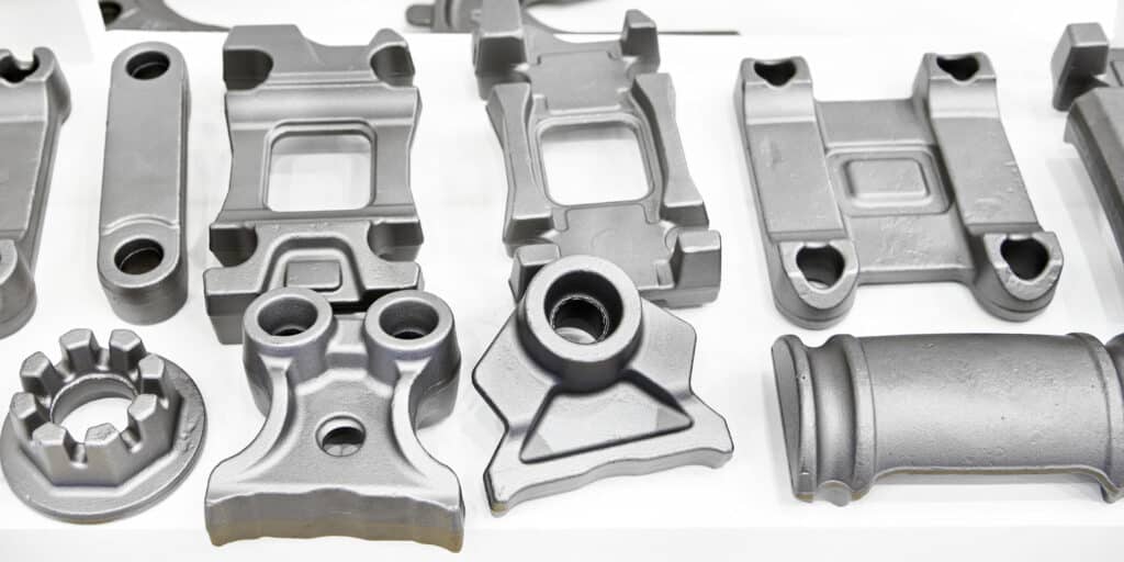
The defining property is constant wall thickness. Where a machined or cast component varies its section freely, a sheet metal part keeps the gauge it was rolled to and gains stiffness from geometry — bends, flanges, ribs, and hems — rather than from mass. That makes it the lightest and cheapest way to build most brackets, housings, and panels, and it makes thickness the first specification on every drawing.
| Gauge Band | Typical Thickness | Common Parts |
|---|---|---|
| Foil / light | 0.2–0.5 mm | EMI shield cans, springs, contacts |
| Standard | 0.5–1.5 mm | Brackets, enclosures, panels |
| Structural | 1.5–3.0 mm | Chassis, mounting plates, guards |
| Heavy | 3.0–6.0 mm | Machine bases, load brackets |
The 0.5–1.5 mm band carries most of the world’s electronics and appliance hardware, and it is where the thin-sheet thread problem (covered below) lives. KeyFix produces this spectrum through its stamping capability, with representative work across the product portfolio.
What Do Common Sheet Metal Part Types Demand?
Each part family carries one specification that dominates its drawing. Knowing which one saves a review cycle.
| Part Type | The Dominant Spec | Watch-Outs |
|---|---|---|
| EMI shield can | Contact-finger spring force; plating continuity | Burr-free contact edges |
| Enclosure / panel | Cosmetic face grade; protective film side | Grain direction visible after brushing |
| Mounting bracket | Hole-pattern position | Keep the pattern on one flange |
| Chassis plate | Flatness under hardware load | Stress-relieve after heavy piercing |
| Deep-drawn cup / shell | Wall thinning at the radius | Draw-ratio limits per stage |
| Spring clip / contact | Temper and fatigue life | Bend ⊥ grain is mandatory, not preferred |
A drawing that leads with its dominant spec — “cosmetic Class A this face” or “pattern ±0.1 mm this flange” — gets a sharper quote than one that tolerances everything equally, because the die maker knows where to spend the tooling budget.
Which Manufacturing Process Fits Your Volume?
Four routes make sheet metal parts, and the right one is almost purely a volume decision.

| Route | Tooling Cost | Per-Piece Cost | Tolerance | Sweet Spot |
|---|---|---|---|---|
| Laser cut + press brake | None | High | ±0.1 mm cut / ±0.3 bend | 1–500 pcs, prototypes |
| Turret punch + brake | Low (standard tools) | Medium | ±0.1 mm | 200–2,000 pcs |
| Progressive-die stamping | High (dedicated die) | Lowest | ±0.05 mm | 1,000–1,000,000+ |
| Deep drawing | High | Low | ±0.1 mm | Cups, cans, shells at volume |
The crossover matters more than the categories: once lifetime volume clears roughly 1,000–5,000 pieces, a progressive die amortizes and every subsequent part costs a fraction of its laser-cut twin — because blanking, piercing, forming, and cutoff all happen in one die at 80 strokes per minute, and bends formed in-die repeat with die precision rather than operator skill. KeyFix supplies hard-tooled stamping as a core process, supports tool-free prototype routes so designs can iterate before steel is cut, and adds machined features — milled faces, tight bores — through its 32-machine CNC line when a stamped part needs one surface the die cannot deliver.
Two hybrid routes round out the map. Stamped-then-machined parts take die economics for the blank and profile, then pick up one milled datum face or a bored hole on the CNC line — common on motor mounts where a bearing seat wants ±0.02 mm the press cannot hold. Stage-tooled programs run a simple blank die first and add forming stations as volume proves out, spreading tooling cash across the ramp instead of betting it all before launch.
💡 Engineer’s Note: Prototype in the tool-free route, but freeze the drawing against progressive-die rules from day one — die-friendly bend radii, hole-to-bend spacing, and a carrier-strip edge. Teams that prototype “laser-optimistic” geometry routinely face a redesign at the volume handoff, which costs more than the prototypes did.
What Are the Core Design-for-Manufacturing Rules?
Sheet metal DFM compresses into a handful of thickness-multiples. Hold them and the part quotes clean; violate them and every piece needs hand rework.
| Rule | Guideline | Why |
|---|---|---|
| Inside bend radius | ≥ 1.0 × t (ductile); ≥ 2× t for hard tempers | Below this, the outer fiber cracks |
| Bend vs. grain direction | Bend line ⊥ rolling grain where possible | Bending along grain invites cracking |
| Minimum hole diameter | ≥ 1.0 × t | Smaller punches snap |
| Hole-to-bend distance | ≥ 3.0 × t + bend radius | Closer holes stretch oval |
| Hole/slot to edge | ≥ 2.0 × t | Prevents edge bulge and tearing |
| Minimum flange height | ≥ 4.0 × t | Shorter flanges won’t form squarely |
| Corner relief at bends | Notch ≥ t wide at intersecting bends | Stops tearing at the junction |
The flat-pattern arithmetic behind bending is the K-factor: metal stretches on the outside of a bend and compresses inside, so the neutral axis sits at roughly 0.33–0.5 × t from the inner face depending on radius and material. Your manufacturer computes the flat blank from it; your job is only to dimension the finished part and let the die do the math.
⚠️ Common Pitfall: A mounting hole placed 2t from a bend line comes out egg-shaped on every part — the forming operation drags material toward the bend and the hole stretches with it. Either move the hole to 3t-plus-radius, or punch it after forming with a cam station, which adds die cost. The free fix is on the drawing; the expensive one is in the tool.
Formed geometry is verified against these rules optically — hole positions and profiles by 2D video measuring, bend angles and twist by Shining3D 3D scanning — under KeyFix’s inspection standards program.
Which Stiffening Features Replace Thickness?
Because gauge is constant, stiffness comes from geometry — and the die adds these features for pennies once tooling exists.
| Feature | Stiffness Effect | Die Cost | Typical Use |
|---|---|---|---|
| Bend / flange | Largest single gain — turns a plate into a beam | In-die, minimal | Every bracket |
| Rib (embossed bead) | 2–5× panel stiffness along its length | One form station | Large flat panels |
| Hem (folded edge) | Stiff, safe, touch-friendly edge | One station | Enclosure openings |
| Louver | Stiffens while venting airflow | Lance-and-form station | Electronics housings |
| Embossed boss | Local stand-off + rigidity around a hole | One station | Mounting points |
| Corner gusset (drawn) | Locks two flanges square | Form station | Load-bearing corners |
The economic point: adding a rib to a stamped panel costs one die station once; upgauging the same panel from 1.0 to 1.5 mm costs 50 % more material on every part forever. Stiffen with the die, not the mill order. Where a design still flexes, a hem doubles the edge and a pair of diagonal beads usually ends the discussion.
How Do You Put Threads in Thin Sheet?
Here is the problem no generic sheet metal page spells out: an M4 thread has a 0.7 mm pitch, so a tapped hole in 1.0 mm stock engages barely two threads — and two threads strip. Every serious sheet design uses one of four escapes.
| Method | How It Works | Engagement Gained | Best Use |
|---|---|---|---|
| Extruded (flanged) + tapped hole | Punch draws a collar, then tap it | ~3× sheet thickness | Cheapest; mid-duty threads in 0.8–2 mm |
| Self-clinching nut / stud / standoff | Knurled collar cold-flows into a punched hole | Full nut-body engagement | The default for electronics and enclosures |
| Weld nut (projection) | Nut welded over the hole | Full engagement | Automotive body, heavy loads |
| Rivet / blind nut | Pulled to grip from one side | Full engagement | Closed sections, field installation |
Self-clinching hardware deserves its own discipline. It works by displacing sheet material into the fastener’s undercut, which imposes three specs the drawing must state: the punched hole diameter (to the hardware maker’s table, no deburring of that hole), a sheet softer than the fastener (clinching into hard stainless demands hardened 400-series hardware), and installation from the correct side with a squeezing press, not a hammer blow.
The hardness rule has numbers: standard-steel clinch hardware needs sheet at or below roughly 70 HRB to flow properly; on stainless sheet, specify hardened stainless hardware rated for it, or the knurl skids instead of biting. Installation is a squeeze of a few kilonewtons applied squarely, with the panel supported so the force seats the fastener without bowing the sheet around it.
This is where a fastener manufacturer’s view pays off directly: KeyFix cold-forges self-clinching studs, nuts, and standoffs on its own heading lines — see the cold forging capability and CNC parts portfolio — and stamps the sheet they install into. Sourcing both from one system means the punched hole, sheet hardness, and hardware knurl are matched by the same engineering owner instead of negotiated between two vendors after the first stripped joint.
📋 Spec Tip: For every clinch position, the drawing needs three items: hardware part number, hole diameter with tolerance, and the installation side. “M4 PEM-style nut, Ø5.41 +0.08/-0, install far side” is buildable; “tapped M4” in 1 mm stock is a warranty claim.
Which Materials and Finishes Suit Sheet Metal Parts?
| Material | Formability | Corrosion | Notes for Sheet Work |
|---|---|---|---|
| Cold-rolled steel (1018-class) | Excellent | Needs coating | The cost baseline for brackets |
| Stainless 304 | Good (work-hardens) | Excellent | Springback is higher — die must compensate |
| Stainless 316 | Good | Outstanding | Washdown and coastal enclosures |
| Aluminum 6061 | Good in O/T4; T6 cracks tight bends | Good | Spec temper or generous radius |
| Brass | Excellent | Excellent | Conductive shields, decorative |
| Copper C110 | Excellent | Patinas | Bus bars, grounding straps |
Two material behaviors dominate sheet outcomes. Springback: stainless and high-strength stock relax a few degrees after forming, so dies overbend to compensate — a reason bend-angle consistency belongs to hard tooling. Temper: 6061-T6 that machines beautifully will crack on a 1t bend; order it in O or T4 temper and age afterward, or open the radius.
One more coil-buying decision hides here: pre-galvanized steel versus coating after stamping. Pre-galv coil is cheaper and skips a process step, but every punched hole and cut line exposes bare steel that rusts first; zinc-nickel or DACROMET applied after forming seals edges and holes too. Interior brackets tolerate pre-galv; anything facing weather or washdown earns the post-process coating. Both routes run under the same lot traceability, so the choice is environmental, not administrative.
Coil and sheet chemistry is confirmed on receipt by SPECTRO optical emission spectrometry through KeyFix’s raw material control — the gate that catches a hard-temper coil sold as forming grade before it cracks a production run. Finishing runs zinc-nickel and DACROMET in-house (validated beyond 1,000 hours neutral salt spray), with powder coating and anodizing available under the same traceability.
What Tolerances Are Realistic on Stamped Parts?
Sheet tolerance has two regimes, and mixing them up is the most common drawing error in the category.
| Feature Class | Realistic Tolerance | Why |
|---|---|---|
| Punched hole diameter | ±0.05 mm | Die-cut geometry |
| Hole-to-hole, same die station | ±0.05 mm | One punch plate, one truth |
| Hole-to-hole, across stations | ±0.1 mm | Strip progression adds up |
| Any dimension across a bend | ±0.2–0.5 mm | Springback + radius variation |
| Bend angle | ±0.5–1° | Material lot variation |
| Flatness | 0.2–0.5 mm per 100 mm | Residual stress after forming |
The rule that falls out: put every critical relationship on one side of one bend, ideally punched in one station. Datum holes that live on opposite flanges inherit the bend’s ±0.3 mm and the angle’s ±1°, and no supplier on earth can inspect that away.
For truly three-dimensional formed parts, a profile-of-a-surface callout referenced to the mounting holes says what pages of coordinate dimensions cannot: the whole formed shape must sit within a band — typically 0.5 mm — of nominal. It is also the callout a 3D scan verifies natively, so the drawing and the inspection method finally speak the same language.
How Do Burrs and Edge Condition Affect Assembly?
Every punched edge has two faces: a smooth roll-over side where the punch entered and a burr side where it exited. Which face ends up outward is an assembly and safety decision, not an accident.
| Concern | Rule of Thumb |
|---|---|
| Operator-touch edges | Burr inward, or hem the edge |
| Gasket / sealing faces | Burr away from the gasket |
| Electrical contact points | Burr side contacts — the sharp edge bites through plating |
| Stacked parts | Mark the burr side; burrs seat first |
Burr height grows with punch wear, so it doubles as the die’s health gauge: a drawing note of burr ≤ 10 % of thickness gives incoming inspection a number and the toolroom a sharpening trigger before dimensions ever drift.
How Are Stamped Sheet Metal Parts Produced and Verified?
| Step | What Happens | KeyFix Capability |
|---|---|---|
| Coil verification | Grade and temper confirmed by OES | SPECTRO (Germany), 100% of heats |
| Progressive stamping | Blank → pierce → form → cutoff in one die | 50–300 T presses, 80 strokes/min, ±0.05 mm |
| Deburr | Tumble or brush; burr side tracked | Controlled, documented |
| Hardware insertion | Self-clinching nuts/studs squeezed in | Matched in-house hardware |
| Finishing | Zn-Ni / DACROMET; powder coating available | 1,000+ hr salt spray verified |
| Verification | Profiles optical; formed geometry scanned | 2D video measuring + Shining3D 3D scanning, Mitutoyo gauge library, 100% optical sorting |
Formed parts are the case where 3D scanning outperforms touch methods: a scan captures the whole bent geometry — angles, twist, flange heights — in one pass and overlays it on the CAD as a color map, which is how bend problems get diagnosed in minutes instead of gauge-building weeks. Delivered stamping programs appear in KeyFix’s project case studies.
Need a quote on stamped parts or clinch-hardware assemblies? Send your STEP file or drawing to KeyFix — DFM review and quotation within 48 hours. Get a quote or email sales@keyfixpro.com.
How Do You Qualify a Sheet Metal Supplier?
Beyond the machine list, five checks separate a stamping house you can build a program on from one you can’t. Die ownership and maintenance: ask who cuts and maintains the tooling, and see the sharpening records — a dull punch shows up as burr height long before it shows up as dimension. Material gate: coil verified by spectrometer, not by the sticker on the crate. Formed-part measurement: 3D scanning or dedicated checking fixtures for anything with a bend; calipers cannot inspect twist. Hardware discipline: if the part carries clinched fasteners, the supplier should control hole size, sheet hardness, and installation force as one specification. Documented quality: outgoing defect rate stated in writing — KeyFix holds below 25 PPM at AQL 0.4 under the IATF 16949 / ISO 9001 / ISO 14001 system described in its company background, serving stamped and hardware-integrated programs across machinery applications.
Reference standards keep the paperwork unambiguous: cold-rolled steel per ASTM A1008 and stainless strip per ASTM A666, with general tolerances per ISO 2768.
What Are the Logistics and Shipping Terms?
KEYFIX manufactures in its own plant in Guangdong Province, near South China’s export ports.
| Term | Detail |
|---|---|
| Manufacturing location | Guangdong Province |
| Standard shipping term | FCA at our Guangdong plant |
| Sea freight term | FOB Shenzhen Yantian Port |
| Prototype lead time | 7–14 business days (tool-free route) |
| Die tooling lead time | 3–6 weeks for progressive dies |
| Production lead time | 4–6 weeks after sample approval |
Frequently Asked Questions
At what volume does stamping beat laser cutting and bending?
Typically from 1,000–5,000 lifetime pieces, where the progressive die amortizes. Below that, tool-free laser-and-brake routes win; above it, per-piece cost drops several-fold and repeatability improves at the same time.
What is the minimum bend radius for a sheet metal part?
About 1× material thickness for ductile stock (cold-rolled steel, annealed aluminum, brass), and 2× or more for hard tempers and stainless. Tighter radii crack the outer fiber; when in doubt, open the radius — it costs nothing.
How do I get a strong thread in 1 mm sheet?
Not by tapping the sheet — that yields about two threads. Use an extruded-and-tapped hole for light duty, a self-clinching nut or stud for the general case, or a weld nut for heavy loads. Specify the clinch hole diameter and installation side on the drawing.
What is the minimum order quantity and tooling cost?
Tool-free prototypes run from 10–100 pieces. Progressive-die production typically starts at 1,000–5,000 pieces, with the die quoted separately and amortized over the program. Contact sales@keyfixpro.com for numbers on your geometry.
What certifications and documentation apply?
IATF 16949, ISO 9001, and ISO 14001. Orders ship with coil material certificates (OES-verified), dimensional reports from video measuring or 3D scanning, burr-side records, and coating documentation where applicable.
What shipping terms apply for international orders?
Standard shipping is FCA at our Guangdong plant, with sea freight as FOB Shenzhen Yantian Port from our Guangdong production base.
If your next program needs sheet metal parts — stamped brackets, shields, chassis plates, or hardware-integrated assemblies with the clinch fasteners forged under the same roof — send your drawing to KeyFix for a free DFM review and a quotation within 48 hours. Explore the product portfolio or contact KeyFix at sales@keyfixpro.com.
Author: KeyFix Engineering Team Published: July 5, 2026 Last Updated: July 5, 2026