Custom PCB standoffs hold a circuit board at an exact height above a chassis or another board. They set the gap for a mezzanine connector, keep components clear of metal, and often carry the ground path. This guide explains how length tolerance feeds the board stack, how to choose material and plating, and when cold heading beats CNC turning on cost.
Key Takeaways
- A PCB standoff is a spacer that holds a board at a fixed distance, using either a female thread at both ends (female-female) or a male stud at one end (male-female).
- Standoff length is the largest single contributor in most board-to-board stack chains. Catalog parts often hold ±0.1 mm, while CNC-turned custom PCB standoffs can be specified to ±0.005 mm on critical length.
- Brass to ASTM B16/B16M with nickel plating is the default for conductive standoffs. Stainless steel suits corrosive or high-load mounts. Anodized aluminum insulates unless the contact faces are masked.
- Turning from hex bar is economical from a single prototype up. Cold heading only pays back once annual volume per size is high enough to amortize the tooling.
Contents
- What is a PCB standoff?
- Which standoff type fits your board?
- How does standoff length tolerance affect PCB stack height?
- Which material and plating should you choose?
- When does cold heading beat CNC turning?
- What standards and inspections apply?
- What should a custom PCB standoffs RFQ include?
- Frequently Asked Questions
What is a PCB standoff?
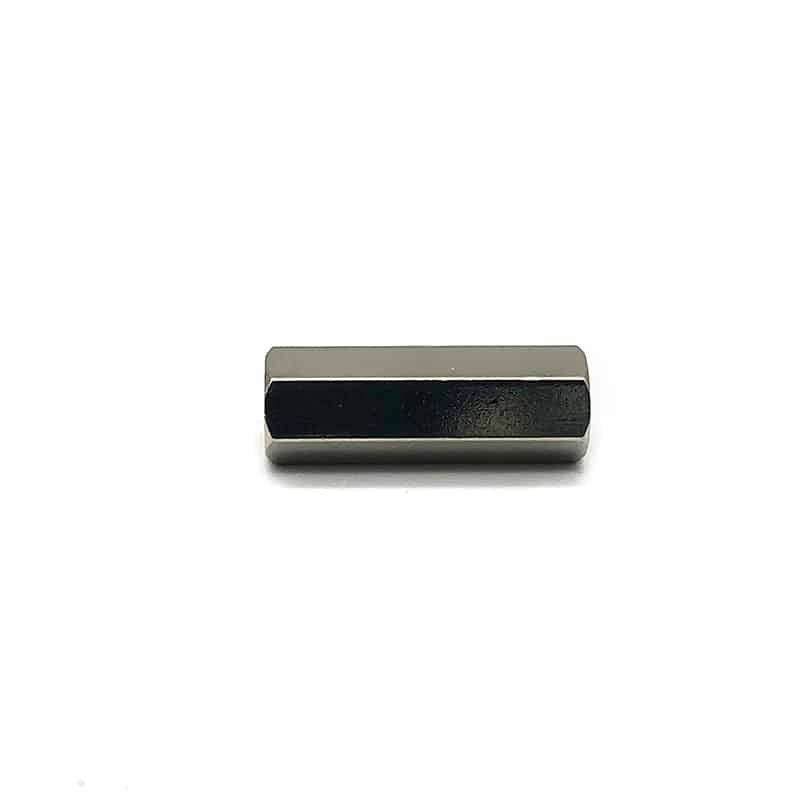
A PCB standoff is a threaded spacer, usually hexagonal or round, that fixes a printed circuit board at a defined distance from a panel, heat sink or second board. The hex lets the standoff be held with a nut driver. The internal or external threads take the mounting screw, and the end faces set the height. Standoffs differ from plain spacers because they carry thread and clamp load.
In an assembly, the standoff does three jobs: it positions the board in Z, carries the screw clamp load, and often conducts chassis ground. A part that fails any one of them causes a field problem, even if it measures correctly on a caliper.
Which standoff type fits your board?
Choose the standoff type by how the board is assembled and serviced. Female-female standoffs take a screw from each side. Male-female standoffs screw directly into a tapped boss or another standoff. Swage and self-clinching types are permanently fixed into sheet metal. The table compares the common types used in custom PCB standoffs programs.
| Standoff type | Thread configuration | Typical use | Watch-outs |
|---|---|---|---|
| Female-female hex | Internal thread both ends | Board-to-chassis, board-to-board with screws | Two screws per joint; check screw length against thread depth |
| Male-female hex | External stud one end, internal other end | Stacking several boards, mounting into tapped bosses | Stud length must not bottom in the mating thread |
| Male-male | External stud both ends | Front panels, spacer columns with nuts | Harder to align; needs nuts or tapped holes on both sides |
| Round, plain or knurled | Any of the above | Tight layouts where a hex would hit components | Needs a slot or cross-hole if it must be driven |
| Self-clinching or swage | Pressed into sheet metal | Permanent mounts in thin chassis panels | Panel hardness and hole size control retention |
Spec Tip: In thin sheet metal, a loose standoff can also mount on self-clinching nuts.
The next table lists common hex sizes by thread. These are typical catalog values, so confirm the across-flats on your drawing.
| Thread | Typical hex across flats | Common length range | Typical application |
|---|---|---|---|
| M2 | 3.5–4.0 mm | 3–20 mm | Small modules, sensor boards |
| M2.5 | 4.5–5.0 mm | 3–30 mm | Single-board computers, compact controllers |
| M3 | 5.0–5.5 mm | 3–50 mm | General PCB mounting, the most common size |
| M4 | 7.0 mm | 5–60 mm | Power boards, heavier assemblies |
| M5 | 8.0 mm | 8–80 mm | Busbar supports, large chassis mounts |
How does standoff length tolerance affect PCB stack height?
Standoff length tolerance adds directly to the board-to-board gap, so it is usually the largest single term in the stack. When a mezzanine connector has a fixed mated height, the standoff must match that height closely. Otherwise the connector is either pulled apart or compressed, and the board flexes around it.
Consider an illustrative two-board stack joined by a 10 mm mated connector. The chain has four terms:
- Standoff length: catalog ±0.10 mm, or CNC-turned ±0.02 mm on request.
- Seating variation from burrs, plating build-up and end-face flatness: roughly ±0.03 mm.
- Connector mated-height tolerance, taken from the connector datasheet.
- Board warp near the connector, governed by the board fabrication spec.
With a catalog standoff, the first two terms alone allow 0.13 mm of error, which can use most of a connector’s float before warp is counted. A ±0.02 mm standoff with square, burr-free end faces brings them to about 0.05 mm. That is why the critical dimension on custom PCB standoffs is length and end-face squareness, not hex size.
Engineer’s Note: Put the length tolerance on the drawing as a functional requirement, for example “overall length 10.00 ±0.02 mm, end faces perpendicular to thread axis within 0.02 mm”. A bare “10 mm” invites the default catalog tolerance.
Thread depth is the second trap. A screw longer than the female thread depth bottoms out and clamps nothing. Specify a minimum full-thread depth and check screw length for each board thickness; boards are commonly 1.6 mm with a fabrication tolerance near ±10 %.
Which material and plating should you choose?
Choose the material for custom PCB standoffs by load, environment and whether the standoff must conduct. Nickel-plated free-cutting brass is the default for conductive hex standoffs: it machines cleanly, conducts well and resists tarnish. Stainless steel suits higher loads and corrosive sites. Aluminum saves weight, but anodizing makes it an insulator.
| Material | Strength and wear | Electrical behavior | Best fit |
|---|---|---|---|
| Brass C36000 (ASTM B16/B16M), nickel plated | Moderate; threads strip at lower torque than steel | Good conductor; nickel keeps contact resistance stable | General electronics, ground paths, most brass standoffs |
| Stainless 303 / 304 / 316 | High; resists galling with correct lubrication | Conductive but higher contact resistance | Outdoor, marine, high clamp load |
| Aluminum 6061-T6, conductive conversion coating | Moderate; light | Conductive at the contact faces | Weight-sensitive enclosures |
| Aluminum 6061-T6, anodized | Moderate; hard surface | Insulating unless faces are masked | Cosmetic parts that must not ground |
For brass standoffs sold into Europe, leaded free-cutting brass relies on RoHS exemption 6(c), which allows copper alloys with up to 4 % lead by weight. Directive (EU) 2025/2364, which amends the RoHS Directive 2011/65/EU, sets that exemption to expire on 30 June 2027. Programs with a long production life should evaluate low-lead brass now.
Common Pitfall: Anodized aluminum standoffs are often specified for appearance, and the ground path then fails at the end face. If the standoff must carry ground, mask both end faces or specify a conductive conversion coating instead.
KEYFIX machines custom PCB standoffs from the alloys on our raw material page and checks composition on a SPECTRO (Germany) OES spectrometer.
When does cold heading beat CNC turning?
CNC turning from hex bar is the economical route for custom PCB standoffs at prototype and low-to-medium volume. Turning needs no dedicated tooling, so even one part can be made, and the hex comes from the bar rather than being machined. Cold heading becomes cheaper only when annual volume per size is high and the design is stable.
| Factor | CNC turning from hex bar | Cold heading plus secondary operations |
|---|---|---|
| Tooling | None beyond standard inserts and taps | Dedicated dies per size, amortized over volume |
| Minimum quantity at KEYFIX | No MOQ, from a single prototype | Typically 5,000–10,000 pcs per size |
| Length tolerance | ±0.005 mm achievable on critical length | Tighter features need a secondary turning operation |
| Material waste | Higher; chips from drilling and parting | Low; cold forging typically uses 95 %+ of the input wire |
| Design changes | Program edit, fast | Die changes, slow and costly |
| Best fit | Prototypes, many variants, tight tolerance | Stable high-volume sizes |
The crossover depends on part length, material and how many sizes share a die set. When volume makes cold heading plausible, KEYFIX quotes both routes and shows tooling cost separately.
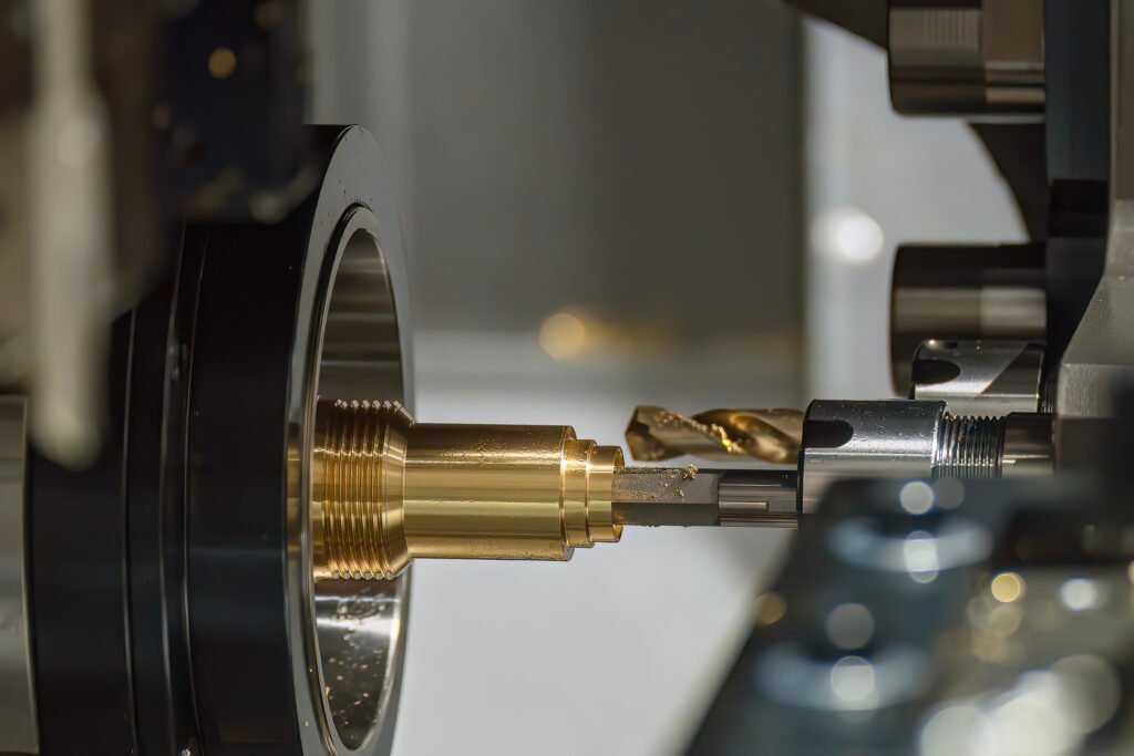
KEYFIX turns custom PCB standoffs on 32 CNC machines, including STS H46 and H52 CNC lathes. Cold-headed versions run on 25 cold heading machines. See our CNC production capability and cold forged parts pages for the process detail, or our guide to brass CNC turned parts for brass-specific machining notes.
What standards and inspections apply?
No single standard covers custom PCB standoffs, so the drawing borrows from thread, material and compliance standards:
| Standard | What it covers | Typical callout |
|---|---|---|
| ISO 965-1:2013 | Metric thread tolerances | Internal 6H, external 6g |
| ASTM B16/B16M-24 | Free-cutting brass rod for screw machines | Alloy C36000, temper as agreed |
| Directive 2011/65/EU (RoHS) | Restricted substances | Declaration per part number |
At KEYFIX, threads are checked with go/no-go plug and ring gauges from M1.2 to M30. Length and hex are measured on 2D video measuring equipment and 145 Mitutoyo precision gauges. Outgoing inspection runs at AQL 0.4 against a target below 25 PPM, under IATF 16949 (audited by NQA). Our inspection standards page lists the full equipment.
What should a custom PCB standoffs RFQ include?
A complete RFQ lets a supplier quote once, without a round of questions:
- Standoff type: female-female, male-female, male-male or round.
- Thread size and class, for example M3 6H internal and M3 6g external.
- Hex across flats, or round diameter and any driving feature.
- Overall length with tolerance, plus end-face perpendicularity if the stack is critical.
- Minimum full-thread depth for each internal thread, and stud length for male ends.
- Material grade and the RoHS or low-lead requirement.
- Plating, thickness, and whether the end faces must stay conductive.
- Annual quantity per size, so cold heading can be evaluated against turning.
KEYFIX usually returns a quotation and DFM feedback within 48 hours of receiving a complete drawing. Samples typically take 7–14 business days.
Frequently Asked Questions
What is the difference between male-female and female-female standoffs?
A female-female standoff has an internal thread at both ends and takes a screw from each side. A male-female standoff has an external stud at one end, so it screws straight into a tapped hole, a nut or another standoff. Male-female parts are the usual choice for stacking several boards in a column.
What size standoff is most common for PCBs?
M3 is the most common thread for PCB standoffs, usually with a 5.0 or 5.5 mm hex. M2.5 is common on single-board computers and compact controllers. M4 and larger sizes are used on power boards and heavier assemblies.
Are brass standoffs conductive?
Yes. Brass conducts electricity, and nickel plating keeps the contact resistance stable over time, so nickel-plated brass standoffs are often used as ground paths. Anodized aluminum standoffs are not conductive unless the end faces are masked or a conductive conversion coating is used.
How tight can the length tolerance be on custom PCB standoffs?
Catalog standoffs commonly hold about ±0.1 mm on length. CNC-turned custom PCB standoffs can be specified to ±0.005 mm on a critical length when the stack requires it. Most board-to-board stacks are well served by ±0.02 mm with square, burr-free end faces.
Is there a minimum order quantity for custom PCB standoffs?
KEYFIX has no MOQ for CNC-turned custom PCB standoffs, from a single prototype to production runs. Cold-headed standoffs typically start at 5,000–10,000 pieces per size because of the tooling. Samples typically take 7–14 business days, and production typically takes 4–6 weeks after sample approval.
Send the drawing for your custom PCB standoffs, or the board stack-up, to KEYFIX for a DFM review. We usually reply within 48 hours of receiving a complete drawing, with a quotation for CNC turning and, where volume allows, cold heading.