
Aluminum reducing bushings solve a problem that appears on almost every machine build: a hole is the wrong size for the shaft, pin, or fastener that has to go through it. A reducing bushing drops into the oversized bore and presents a smaller one, converting a Ø20 mm hole into a Ø12 mm seat without remaking the part. Step bushings add a shoulder that also sets axial position. But there is a distinction that decides whether the part succeeds or seizes, and most catalogues skip it entirely: an aluminum bushing is a dimensional adapter, not a bearing. This guide covers that boundary, press-fit interference, wall thickness limits, the thermal expansion mismatch that loosens aluminum-in-steel joints, alloy selection, anodising effects on fit, and sourcing.
TL;DR — Key Takeaways
- A reducing bushing converts one bore size to another; a step (shoulder) bushing also locates axially against the host face.
- Aluminum galls against steel under sliding contact — if the shaft rotates or slides, specify a bronze, polymer, or lined bushing instead.
- Press-fit interference typically runs 0.0005–0.002 × bore diameter; too little spins, too much yields the thin aluminum wall.
- Aluminum expands roughly twice as much as steel (≈23 vs 12 μm/m·K), so a heated joint loses shaft clearance control and can lose retention.
- Anodising grows the surface — Type II adds roughly half its thickness outward — so fits must be dimensioned for the plated or anodised condition.
What Is a Reducing Bushing and What Is a Step Bushing?
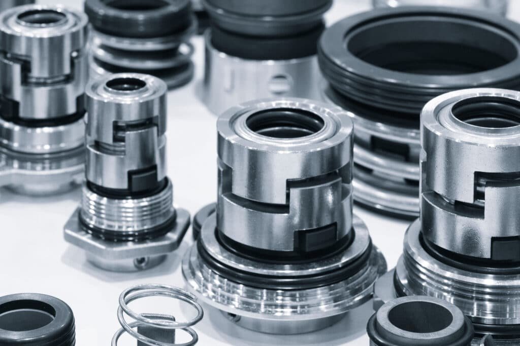
Aluminum reducing bushings and step bushings are both simple sleeves whose job is dimensional conversion, but they locate differently.
| Type | Geometry | What It Controls |
|---|---|---|
| Reducing bushing | Plain cylindrical sleeve | Bore size only — radial conversion |
| Step (shoulder) bushing | Sleeve with an integral flange | Bore size plus axial position |
| Flanged bushing | Larger flange, thinner sleeve | Bore plus load spreading on the face |
| Double-step bushing | Two diameters on the outside | Adapts two bores at once |
| Slotted / split bushing | Cut along its length | Compresses to fit; field-adjustable |
| Threaded insert bushing | Internal thread in the bore | Converts a clearance hole to a threaded one |
The step version earns its cost whenever depth matters. A plain reducing bushing can be pressed too deep or drift under load; a shoulder gives it a hard stop against the host surface and a defined bearing face. In fixtures, jigs, and pivot assemblies where the axial position of a pin sets the geometry, the shoulder is doing as much work as the bore.
KeyFix machines both forms across its CNC production line at ±0.005 mm, with examples across the CNC parts portfolio and the wider product portfolio.
Why Is an Aluminum Bushing Not a Bearing?
This is the distinction that matters most, and getting it wrong is the leading cause of failed aluminum bushing applications. Aluminum has a strong affinity for steel under contact pressure: the oxide film breaks down at the interface, fresh metal transfers to the shaft, and the pair galls — the same cold-welding behaviour that plagues titanium fasteners. Once galling starts, the bore scores, debris accumulates, and the joint seizes.
| Application | Aluminum Bushing Suitable? | Better Choice If Not |
|---|---|---|
| Static bore reduction (press-fit, no motion) | Yes — the ideal use | — |
| Locating pin seat (occasional assembly) | Yes, with lubrication | — |
| Fastener spacer / standoff | Yes | — |
| Slow oscillating pivot | Marginal — needs liner or anodising | Bronze, PTFE-lined |
| Continuous rotation | No — galls and seizes | Bronze graphite, oil-impregnated |
| High radial load with motion | No | Steel-backed bearing |
Where the shaft does move, three routes rescue the design. Hard anodising (Type III) raises surface hardness substantially and provides a wear layer, adequate for light oscillation. A PTFE or polymer liner inside the aluminum sleeve separates the metals altogether. Or the bushing simply becomes a different material — a bronze or self-lubricating insert carried in an aluminum housing gets both the light weight and the bearing behaviour.
💡 Engineer’s Note: Ask one question before specifying aluminum: does anything move relative to the bore? If the answer is no — the bushing just resizes a hole for a bolt, dowel, or press-fit pin — aluminum is an excellent, light, economical choice. If the answer is yes, aluminum is the wrong material and no amount of lubrication fully fixes it.
How Do You Calculate Press-Fit Interference?
Aluminum reducing bushings are normally retained by interference: the outside diameter is made slightly larger than the host bore, and the elastic squeeze holds it.
| Fit Class | Interference (per unit diameter) | Behaviour |
|---|---|---|
| Light press (locational) | 0.0002–0.0005 × D | Hand or arbor press; low retention |
| Standard press | 0.0005–0.001 × D | The general-purpose range |
| Heavy press (force fit) | 0.001–0.002 × D | High retention; risks thin-wall yield |
| Shrink / thermal fit | 0.001–0.002 × D | Cool the bushing, then insert |
For a Ø20 mm bushing in a standard press fit, that is roughly 0.010–0.020 mm of interference — a range you cannot hit without controlling both the bushing OD and the host bore. Specifying an H7 bore on the host part and a matching shaft-basis tolerance on the bushing is the practical route.
Two aluminum-specific cautions apply. Aluminum’s modulus is roughly one third of steel’s, so the same interference generates far less contact pressure than it would between steel parts — aluminum bushings need the upper end of the range for equivalent retention. And because aluminum yields at lower stress, excess interference does not just squeeze the sleeve, it permanently deforms it, shrinking the finished bore below drawing size after insertion.
⚠️ Common Pitfall: Machining the bushing bore to final size before pressing it in. The interference compresses the sleeve and the bore closes — often by a substantial fraction of the interference on a thin wall. Machine the bore after installation, or size it deliberately oversize by the calculated closure. Parts that gauge perfectly on the bench and refuse the shaft after assembly nearly always trace to this.
Bore and OD conformance is verified by 2D video measuring and calibrated Mitutoyo gauges, documented under KeyFix’s inspection standards program.
What Wall Thickness Do Aluminum Reducing Bushings Need?
Wall thickness sets whether the sleeve survives the press-fit and carries load without collapsing.
| Bushing OD | Minimum Practical Wall | Notes |
|---|---|---|
| Up to Ø10 mm | 1.0–1.5 mm | Below this, machining distortion dominates |
| Ø10–25 mm | 1.5–2.5 mm | The common range |
| Ø25–50 mm | 2.5–4.0 mm | Scale with interference |
| Above Ø50 mm | ≥ 4.0 mm | Thin walls chatter and distort in the lathe |
Thin walls create three separate problems: they deflect during machining, giving an out-of-round bore; they yield under press-fit rather than springing; and they offer little material for a shoulder or thread. As a working rule, keep the wall at or above 10 % of the outside diameter for press-fit aluminum bushings, and treat anything thinner as a special requiring workholding review.
[IMAGE SUGGESTION: Cross-section of a step bushing pressed into a plate showing interference at the OD, shoulder contact, wall thickness, and bore closure arrows. Alt text: “Press-fit cross-section of an aluminum step bushing showing interference and wall thickness”]
How Does Thermal Expansion Affect the Fit?
Aluminum expands roughly twice as fast as steel, and that mismatch changes fits whenever temperature moves.
| Material | Thermal Expansion (μm/m·K) | Relative |
|---|---|---|
| Aluminum 6061 | ≈ 23.6 | ~2× steel |
| Brass | ≈ 20 | ~1.7× |
| Stainless 304 | ≈ 17 | ~1.4× |
| Carbon steel | ≈ 12 | Baseline |
| Cast iron | ≈ 11 | Baseline |
The consequences run in two directions, and it is worth being precise about which is which. An aluminum bushing pressed into a steel housing gets tighter as the assembly heats — the sleeve wants to grow more than the bore that contains it, raising contact pressure and, at extremes, yielding the aluminum. Conversely, a steel shaft running in an aluminum bore sees clearance increase with temperature, because the aluminum bore opens faster than the shaft grows.
Neither is automatically a problem, but both need checking when the assembly runs hot. A joint set to a light press at 20 °C may exceed the aluminum’s yield at 120 °C; a pin fit that is snug when cold may rattle at operating temperature. The 0.001 mm-per-100 mm-per-10 °C order of magnitude is easy to dismiss until the fit tolerance is only 0.02 mm wide.
Which Alloys Suit Aluminum Reducing Bushings?
| Alloy | Yield Strength | Machinability | Best Use |
|---|---|---|---|
| 6061-T6 | ~275 MPa | Very good | The general-purpose default |
| 6063-T5 | ~145 MPa | Good | Extruded stock, light duty |
| 2024-T351 | ~325 MPa | Excellent | Higher strength, poorer corrosion |
| 7075-T6 | ~505 MPa | Good | Highest strength; press-fit heavy duty |
| 5052-H32 | ~195 MPa | Fair (gummy) | Corrosion-resistant, formed parts |
6061-T6 covers most work: it machines cleanly, anodises well, and carries enough strength for standard press fits. Where the interference is heavy or the bushing takes real radial load, 7075-T6 nearly doubles the yield strength — worth the cost premium in thin-wall or high-retention designs. 2024 is strong and machines beautifully but corrodes readily, so it needs protective finishing.
Incoming bar is confirmed by SPECTRO optical emission spectrometry through KeyFix’s raw material control process — the check that catches a 6063 bar sold as 6061 before a press-fit design loses half its retention.
How Does Anodising Change the Dimensions?
This detail derails more aluminum bushing programs than any other finishing question. Anodising is a conversion coating: part of the film grows into the material and part grows outward. For Type II anodising, roughly half the total thickness builds up on the surface, so a 20 μm coating adds about 10 μm per surface — meaning an outside diameter grows by roughly 20 μm and a bore shrinks by the same.
| Anodising Type | Typical Thickness | Approx. Dimensional Growth per Surface | Hardness |
|---|---|---|---|
| Type II (decorative/protective) | 5–25 μm | ~50 % of thickness | Moderate |
| Type III (hard anodise) | 25–50 μm | ~50 % of thickness | High — wear resistant |
| Chromate conversion | <1 μm | Negligible | Low |
For a bushing with a 0.02 mm press fit, a Type III coating can consume the entire interference budget or jam a bore that gauged correctly bare.
📋 Spec Tip: State on the drawing whether each dimension applies before or after anodising, and mask bores that must hold tolerance. “Ø12.00 H7 after anodise, bore masked” is buildable; a bare-condition drawing with a hard-anodise note attached is a dispute waiting to happen.
How Are Custom Aluminum Bushings Produced?
| Step | What Happens | KeyFix Capability |
|---|---|---|
| Bar verification | Alloy and temper by OES | SPECTRO (Germany), 100 % of heats |
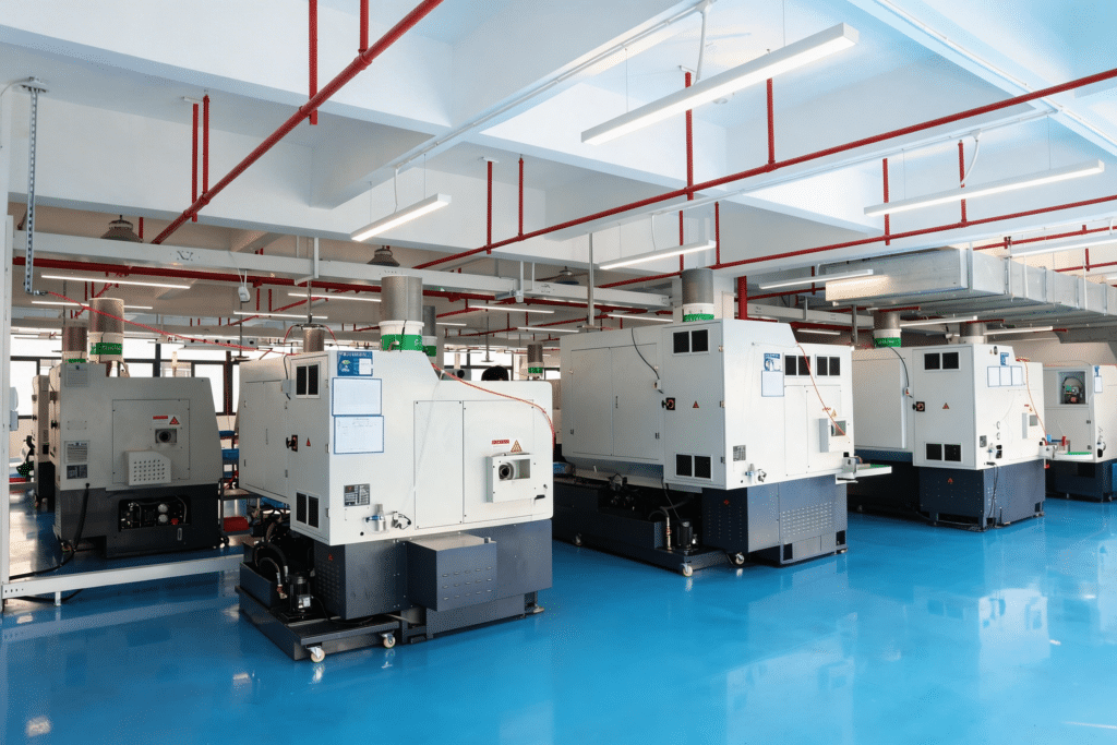
| CNC turning | OD, bore, shoulder in one chucking | 32 CNC machines incl. two 5-axis, ±0.005 mm |
| Live-tool features | Cross holes, flats, slots | Same setup, concentricity preserved |
| Deburr | Edge break, lead-in chamfer | Controlled |
| Anodising | Type II or III, masked as specified | Qualified partner lines |
| Verification | OD, bore, concentricity, shoulder | 2D video measuring + Shining3D scanning, Mitutoyo gauges, 100 % optical sorting |
Turning the OD and bore in a single chucking is what makes aluminum reducing bushings concentric — the two surfaces share one spindle axis, so wall thickness stays uniform and the pressed-in bore runs true. Refixturing to cut the bore separately introduces the eccentricity that shows up later as a shaft that binds at one point of rotation. Process detail sits on the technology overview; high-volume near-net blanks come from the cold forging line, and related components from stamping.
Need a quote on custom aluminum reducing or step bushings? Send your drawing or a sample to KeyFix — DFM review and quotation within 48 hours. Get a quote or email sales@keyfixpro.com.
What Should the Drawing Specify?
| Call-Out | What to Specify | Why It Matters |
|---|---|---|
| Alloy + temper | e.g., 6061-T6, 7075-T6 | Strength and press-fit behaviour |
| Outside diameter + fit | With host bore tolerance stated | Sets interference |
| Bore + fit class | e.g., Ø12 H7 | Shaft or pin fit |
| Bore condition | Before or after press-fit | Prevents post-installation closure |
| Shoulder dimensions | Diameter, thickness, face squareness | Axial location |
| Wall thickness | ≥ ~10 % of OD | Machining and yield margin |
| Concentricity | Bore to OD, TIR value | Shaft runs true |
| Anodise + masking | Type, thickness, masked features | Dimensional growth control |
How Do You Qualify a Manufacturer?
| Audit Point | Minimum Requirement | KeyFix Status |
|---|---|---|
| Quality system | ISO 9001 minimum | IATF 16949 + ISO 9001 + ISO 14001 |
| Turning capability | OD and bore in one chucking | 32 CNC machines, ±0.005 mm |
| Material verification | OES per bar lot | SPECTRO OES, 100 % of heats |
| Thin-wall experience | Workholding for low-distortion parts | Documented process |
| Dimensional control | Bore, OD, concentricity measured | 2D video measuring + Mitutoyo gauges |
| Finishing control | Anodise thickness and masking | Qualified partners, documented |
| Outgoing quality | Stated defect rate | <25 PPM at AQL 0.4 |
Aluminum bar follows ASTM B211 and fits follow ISO 286 tolerance classes, under the quality system documented in KeyFix’s company background, with delivered work in the project case studies and machinery hardware programs.
What Are the Logistics and Shipping Terms?
KeyFix manufactures in Huizhou, Guangdong, near South China’s export ports.
| Term | Detail |
|---|---|
| Manufacturing location | Huizhou, Guangdong Province |
| Standard shipping term | FCA Dongguan |
| Sea freight term | FOB Shenzhen Yantian Port |
| Prototype lead time | 7–14 business days (air-expressed) |
| Production lead time | 4–6 weeks after sample approval |
Frequently Asked Questions
Can an aluminum bushing be used as a bearing?
Not for continuous rotation. Aluminum galls against steel under sliding contact and will seize. For static bore reduction, spacers, and locating seats it is ideal; for motion, use bronze, a self-lubricating material, or a PTFE-lined sleeve.
What is the difference between a reducing bushing and a step bushing?
A reducing bushing is a plain sleeve that converts bore size only. A step bushing adds an integral shoulder that also sets axial position against the host face, which matters in fixtures and pivots where depth is functional.
How much press-fit interference should I specify?
Roughly 0.0005–0.001 × diameter for a standard press fit, toward the upper end for aluminum because its lower modulus generates less contact pressure. Control both the bushing OD and the host bore, or the fit is a guess.
Why is my bore too small after pressing the bushing in?
Interference compresses the sleeve and closes the bore. Machine the bore after installation, or size it oversize by the calculated closure. Thin walls close proportionally more.
Does anodising change the fit?
Yes. Roughly half the coating thickness grows outward, so an OD gains about twice that per diameter and a bore loses the same. Mask bores that must hold tolerance and state whether dimensions apply before or after anodising.
What is the minimum order quantity?
CNC-machined aluminum bushings run from 50–100 pieces for prototypes, scaling into the thousands with price breaks. Contact sales@keyfixpro.com for quotations.
If your next assembly needs custom aluminum reducing bushings or step bushings — plain, flanged, double-stepped, or hard-anodised — send your drawing to KeyFix for a free DFM review and a quotation within 48 hours. Explore the product portfolio or contact KeyFix at sales@keyfixpro.com.
Author: KeyFix Engineering Team Published: July 9, 2026 Last Updated: July 9, 2026