A fastener friction coefficient is useful only when the measured quantity and test conditions are clear. Buyers often receive a friction number without knowing whether it describes the threads, bearing surface, or an effective total value. ISO 16047 testing helps characterize tightening behavior, but the resulting report must still be connected to the production joint.
Key Takeaways
- Thread friction, bearing friction, total friction, and the nut factor K are different reported quantities.
- A friction result belongs to the tested material, geometry, finish, lubrication, and mating surfaces.
- ISO 16047:2005, including Amendment 1:2012, has a defined scope and exclusions.
- A coating certificate and a torque wrench reading do not replace a torque/clamp force assessment.
- Specify the acceptance window, sample condition, report content, and change triggers before ordering.
What does a fastener friction coefficient describe?
A fastener friction coefficient describes frictional behavior at a defined contact or through a specified calculation for an assembly. Thread friction concerns the mating threads; bearing friction concerns the rotating contact beneath the head or nut. An effective total value represents combined behavior under its calculation assumptions. These quantities should not be exchanged without explanation.
The first report review is a terminology check. A value labeled only “friction” leaves the measured interface and calculation uncertain. Ask for the symbol, definition, units, and method before comparing results from different suppliers or deciding that one finish is equivalent to another.
Use this terminology table when reviewing a report.
| Reported quantity | Meaning | Interpretation limit |
|---|---|---|
| Thread friction, μth | Friction at the engaged threads | Does not describe the bearing surface |
| Bearing friction, μb | Friction at the rotating bearing contact | Depends on the specified contact pair |
| Effective total friction, μtot | Combined value under the method’s assumptions | Not the arithmetic sum of μth and μb |
| Nut factor, K | Empirical torque to clamp load relationship | Not a coefficient of friction |
LOCTITE’s ISO 16047 assembly guidance distinguishes these reported quantities. A useful purchasing requirement names the quantity needed instead of asking generally for a “low friction coating.” Low friction alone does not define an acceptable clamp load window.
How is the nut factor different from friction?
The nut factor K relates tightening torque, clamp load, and nominal diameter through a simplified empirical expression. It incorporates the behavior of the tested assembly rather than identifying friction at one interface. Converting a K value directly into a thread or bearing coefficient is therefore inappropriate without the relevant geometry, assumptions, and measurement method.
The screening relation is T = K × F × d, where T is torque in N·m, F is clamp load in N, and d is nominal diameter in meters. Rearranging gives F = T / (K × d). This relation is useful for demonstrating sensitivity; it is not a substitute for validating a tightening setting.
The following example uses assumed inputs and is not a production torque recommendation.
| Illustrative condition | Assumed torque | Assumed diameter | Assumed K | Calculated clamp load |
|---|---|---|---|---|
| Condition A | 20 N·m | 0.008 m | 0.20 | 12.50 kN |
| Condition B | 20 N·m | 0.008 m | 0.16 | 15.63 kN |
The calculated clamp load rises by 25% when K changes from 0.20 to 0.16 at the same assumed torque and diameter. That arithmetic does not predict production scatter. It shows why changing a lubricant or finish while leaving the torque setting unchanged can change joint loading.
LOCTITE’s K-factor guidance describes determining K using clamp load and torque measurements. Keep the distinction visible in the drawing: a requirement for μtot is not automatically satisfied by a supplier reporting K.
What does ISO 16047 testing cover?
ISO 16047:2005 specifies conditions for torque/clamp force testing of threaded fasteners and related parts within its scope. Its current published base edition has Amendment 1:2012. Confirm applicability before naming the method on an order, particularly when the fastener forms its mating thread or includes an additional self-locking feature.
The official ISO 16047 listing describes its basic application to carbon and alloy steel metric fasteners and related combinations. It excludes thread-forming screws, additional self-locking features, and set screws or similar parts that are not under tensile stress. An agreed application-specific method may be needed for excluded arrangements.
This scope check prevents an unsuitable test request.
| Fastener arrangement | Initial decision | Required follow-up |
|---|---|---|
| Conventional bolt and nut assembly | Review against the method’s scope | Define specimen and mating components |
| Screw forming its mating thread | Outside the stated scope | Agree a suitable installation test |
| Additional self-locking feature | Outside the stated scope | Define how locking behavior is assessed |
| Non-tensioned set screw | Outside the stated scope | Select a relevant functional assessment |
A test name alone cannot establish equivalence to a vehicle or machine joint. The actual joint may have a different bearing surface, washer, internal thread material, tightening tool, or service environment. Record which conditions are standardized and which deliberately reproduce the application.
Which test conditions change the result?
The tested fastener, mating thread, bearing contact, coating, lubricant, tightening conditions, and sample history can change the result. A fastener friction coefficient should therefore be accompanied by a defined test configuration. Compare reports only after checking those conditions; matching nominal thread size and coating color is insufficient evidence of equivalent tightening behavior.
The configuration review should include all relevant contact and preparation conditions.
| Variable | Information to record | Why it matters |
|---|---|---|
| Fastener geometry | Thread, head, bearing dimensions | Changes the torque and load relationship |
| Mating thread | Material, geometry, condition | Defines the threaded contact pair |
| Bearing contact | Washer or plate, finish, contact condition | Defines the rotating bearing interface |
| Complete finish | Coating, topcoat, lubricant | Influences friction and consistency |
| Sample history | Storage, handling, previous tightening | May change the tested surface condition |
| Test procedure | Speed, evaluation point, deviations | Affects comparability and interpretation |
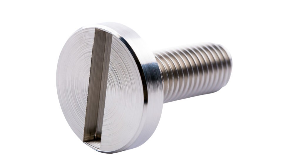
Kistler’s clamp force sensor documentation illustrates the need for suitable mechanical adapters and bearing arrangements in friction testing. The test fixture forms part of the measurement configuration. It should not disappear from the purchasing discussion simply because the final report contains one average number.
The EV motor housing bolt guide shows why a finished joint also needs temperature, housing, and functional assessment. A controlled friction test provides an input to that engineering work; it does not validate the complete housing by itself.
How should a coating or lubricant change be approved?
Approve a coating or lubricant change by reviewing its effect on tightening behavior and the joint’s other functions. The change may influence friction, thread fit, corrosion performance, electrical contact, and handling. Reusing an old torque setting is acceptable only when the responsible engineering review and relevant evidence support the revised configuration.
This change matrix connects the purchasing change to the required review.
| Proposed change | Tightening question | Other requirement to retain |
|---|---|---|
| New topcoat | Is the clamp load relationship still acceptable? | Corrosion and compatibility |
| Added lubricant | Is the load at the current torque still controlled? | Cleanliness and service conditions |
| Different washer or plate | Has bearing friction changed? | Seating and local contact pressure |
| Reworked finish | Does the revised route meet the agreed requirements? | Material and coating process controls |
| New material or geometry | Does the previous test remain representative? | Mechanical and dimensional performance |

See the zinc flake coating guide for specifying the finish as a complete system. Where electroplating and susceptible materials are involved, the hydrogen embrittlement guide addresses a separate process risk. Meeting a friction requirement does not replace those controls.
Typical Scenario: A purchaser approves a visually similar finish from a new source, but tightening produces a different clamp load distribution. Compare the complete surface system and test configuration before changing the assembly setting. A matching salt spray result alone cannot establish equivalent friction behavior.
What should the acceptance window and report contain?
An acceptance requirement should identify the reported quantity, permitted range, evaluation conditions, sample plan, and treatment of individual results. The report should show which parts were tested and how the result was obtained. An average within a range can hide unacceptable individual values unless the agreed acceptance rule explicitly addresses them.
Use this report checklist when qualifying or purchasing coated fasteners.
| Report field | Required content | Review question |
|---|---|---|
| Identification | Part, revision, material and finish lot | Can the result be traced to the shipment? |
| Configuration | Mating thread, bearing contact, lubrication | Does the setup match the requirement? |
| Method | Edition, procedure, relevant deviations | Is the claimed method applicable? |
| Results | Named quantities, individual data, agreed summary | Are the acceptance rules satisfied? |
| Supporting evidence | Relevant torque and clamp load records | Can the calculation be reviewed? |
| Disposition | Deviations and engineering decision | Is acceptance documented? |
Do not copy a universal friction range from a catalog into every drawing. The acceptable range must work with the assembly’s lower and upper load limits, tool capability, geometry, and service requirements. The laboratory should also understand whether the purpose is process comparison or characterization of a particular joint.
What should an RFQ specify for friction verification?
An RFQ should define the part and finish, the friction quantity required, the test configuration, acceptance criteria, and reporting scope. It should also identify the application and planned changes that require revalidation. This allows testing and manufacturing requirements to be quoted together rather than adding an undefined friction certificate after production.
The RFQ package should cover these items.
| RFQ field | Information to provide |
|---|---|
| Part definition | Drawing revision, material, thread and bearing geometry |
| Surface system | Coating, topcoat, lubricant and approved alternatives |
| Test request | ISO 16047 applicability and required reported quantity |
| Configuration | Mating components and standardized or application conditions |
| Acceptance | Range, sample plan, individual result rules and disposition |
| Deliverables | Report, traceability and supporting measurement records |
| Change control | Material, finish, geometry and process change triggers |
KEYFIX supplies custom fastener components using cold heading, thread rolling, and CNC turning. Inspection capabilities include thread go/no-go gauging and Rockwell and Vickers hardness testing. Torque/clamp force and friction verification are arranged through third-party testing laboratories when required.

The inspection standards overview describes related quality controls. Quotation and DFM feedback are usually available within 48 hours of receiving a complete drawing. Send the drawing, finish requirements, and proposed test scope through the contact page.
Frequently Asked Questions
Is the nut factor K equal to the coefficient of friction?
No. K is an empirical torque to clamp load factor for a defined assembly. Thread friction, bearing friction, and effective total friction are separate quantities with their own definitions and calculation conditions.
Does a lower friction value always improve the joint?
No. At an unchanged torque, lower friction can increase clamp load and potentially overload the bolt or mating component. The friction window must fit the validated assembly load limits.
Can a torque wrench alone measure a fastener friction coefficient?
No. A torque reading alone does not establish clamp load or separate the relevant friction contributions. Use a suitable measurement arrangement and the agreed method.
Can a friction report from another bolt size be accepted directly?
Not automatically. Compare geometry, material, finish, mating components, and the method’s assumptions. The responsible engineering review must establish whether the evidence is representative.
Can one report cover unlimited future coating changes?
No. Define the approved surface system and the changes requiring review or revalidation. A previous result does not automatically qualify a different topcoat, lubricant, or processing route.
Does KEYFIX perform torque/clamp force testing internally?
No. Required torque/clamp force and friction verification are arranged through third-party testing laboratories. Agree the method, sample configuration, acceptance criteria, and report scope at quotation.